Installing the UPS System
3-5
Powerware
®
9390 UPS (40–80 kVA) Installation and Operation Manual
S
164201535 Rev A
W A R N I N G
The front ant-tip/shipping bracket must be reinstalled, otherwise injury and damage to the
UPS may result when removing components during service. If the bracket is not reinstalled, the
cabinet may tip and cause serious injury and damage.
12.
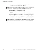
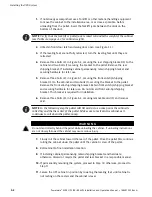
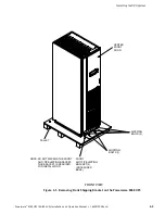
Using retained hardware, reinstall front anti-tip shipping bracket (bracket with
wider base) previously removed to front of UPS cabinet with the angle facing
outward and adjusted level with the floor (see Figure 3-1).
13.
If installing a battery cabinet, proceed to paragraph 3.2.2; otherwise, proceed to
paragraph 3.2.3.
14.
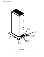
Using retained hardware, reinstall shipping brackets previously removed to front
and rear of UPS cabinet with the angle facing outward (see Figure 3-1 and
Figure 3-2).
15.
If installing a battery cabinet, proceed to paragraph 3.2.2; otherwise, proceed to
paragraph 3.2.3.
3.2.2 Battery Cabinet Installation
To install the battery cabinet, refer to the
Powerware 9390 Battery Cabinet Installation
Manual
listed in paragraph 1.4. Once battery cabinet is installed return to paragraph 3.2.3
to wire the UPS and battery cabinet.
3.2.3 Installing UPS External and Battery Power Wiring
NOTE
The UPS cabinet is shipped with a debris shield covering the ventilation grill
on top of the unit. Do not remove the debris shield until installation is complete.
However, remove shield before operating the UPS. Once the debris shield is removed,
do not place objects on ventilation grill.
NOTE
Remove UPS cabinet top or bottom wire entry conduit landing plate to drill or
punch conduit holes (see Drawing 164201535-6 on page A-14).
1.
If not already open, unfasten front door latch and swing door open.
2.
Slide air filter up and remove from cabinet.
3.
Remove screws securing bottom internal safety shield panel and remove panel to
gain access to input, output, and battery terminals.
4.
If installing power wiring from the top of the cabinet, proceed to Step 5;
otherwise, proceed to Step 7.
5.
Remove screws securing top internal safety shield panel and open panel to gain
access to top entry wireway.
Содержание 9390
Страница 1: ...9390 INSTALLATION OPERATION MANUAL UPS 40 80 kVA www powerware com ...
Страница 13: ...1 1 Powerware 9390 UPS 40 80 kVA Installation and Operation Manual S 164201535 Rev A Section I Installation ...
Страница 37: ...5 5 Powerware 9390 UPS 40 80 kVA Installation and Operation Manual S 164201535 Rev A Section II Operation ...
Страница 137: ......
Страница 138: ... 164201535A 164201535 A ...


