


49
Where:
- Iin-ovl is Overload Input Current (A)
- Pout is Rated Output Apparent Power (VA)
- Vout_p-n is Rated Output Voltage phase-to-neutral (V)
˙
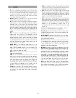
Alarm 2: This alarm indicates that the inverter is overloaded. The
inverter overload appears either when the output current of any
phase is greater than the rated output current
Iout-ovl = Pout / (Vout_p-n * 3)
Where:
- Iout is rated Output Current (A)
- Pout is Rated Output Apparent Power (VA)
- Vout_p-n is Rated Output Voltage phase-to-neutral (V)
or when the total output active power is greater than the following
formula:
Pact_out-ovl = Pout x 0,8
Where:
- Pact_out-ovl is the Overload Output Active Power (W)
- Pout is Rated Output Apparent Power (VA)
˙
Alarm 3: This alarm appears when the input the unit is under main
failure condition and the level of battery is lower than 11,5V/bat.
˙
Alarm 4: This alarm appears when the inverter output voltage
phase to neutral in any phase is out of margins over +/-6%.
˙
Alarm 5: This alarm appears when there is an offset voltage higher
than 5V, in any phase of the inverter output voltage phase to
neutral.
˙
Alarm 6: When the maintenance bypass switch is ON the UPS
inverter will not be available.
˙
Alarm 7: The mains failure occurs when in any phase, the input
voltage phase to neutral is out of the set margins (+15%/–20% by
default) or the input frequency is out of the set margins (± 0,5Hz
by default).
˙
Alarm 8: When the inverter or PFC temperature sensors measure
temperatures over the programmed values (70ºC by default).
˙
Alarm 9: This message appears when the battery switch is OFF
and the DC bus is charged to the battery voltage level, to inform
the user to switch ON the battery switch.
˙
Alarm 10: This Alarm indicates that the bypass input voltage or the
bypass input frequency are out of margins. These margins are
programmable but by default the bypass voltage range is +12%/–
17% and the bypass frequency range is ± 0.5Hz.
˙
Alarm 11: The UPS is on bypass for any reason. It must be
restarted by display keypad.
˙
Alarm 12: This is an alarm for parallel systems. It appears when
some UPS of the parallel system block because the maintenance
bypass switch of any unit is switched ON.
˙
Alarm 13: This alarm indicates that the CAN BUS #1 fails. This
communication channel is used for remote control.
˙
Alarm 14: This alarm indicates that the CAN BUS #2 fails. This
channel is used for data communication between UPS, in a parallel
system.
˙
Alarm 15: This alarm appears at the estimated end of live of the
battery bank. The revision and replacement of some batteries will
be necessary to be done by calling the S.T.S. (Service and
Technical Support) department.
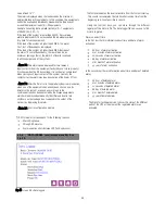
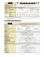
Representation in display
LCD
Alarms
Alarm NO.
Rectifier Overload.
RECTIFIER
1
Inverter Overload.
INVERTER
2
Mains Failure. Battery Low
Level.
3
Inverter Voltage Out of Margins.
4
DC Voltage Detected at the
Output.
5
Maintenance Bypass. Inverter
Not Available.
6
Battery Discharging.
UPS
7
High Temperature. Reduce
Output Load.
8
Battery Switch Open. Switch it
ON.
9
Bypass Failure. Not
Synchronised Inverter.
10
Unit on Bypass. Initialise UPS.
11
Some Unit(s) Blocked due to
Maintenance Bypass.
12
CAN BUS 1 Communication
Failure.
13
CAN BUS 2 Communication
Failure.
14
End of Battery Life.
15
Battery Temperature too High.
16
Battery Test Not Succeeded.
17
Battery Disconnection.
Shutdown & Restart.
18
Mains Phase Rotation. UPS
Start Disabled.
19
Bypass Phase Rotation. UPS
Start Disabled.
20
EEPROM Failure.
77
Input Voltage Wrong. Rectifier
Stop.
RECTIFIER
STOPS
21
Rectifier Desaturation. Rectifier
Stop.
22
DSP Internal Error. Rectifier
Stop.
23
Input Phase Rotation. Rectifier
Stop.
24
DC BUS Voltage Wrong.
68