


27
4.5. OPERATING STRUCTURE OF A PARALLEL SYSTEM.
This Uninterruptible Power Supply Systems s e r i e s , are
designed and thought for its «parallel» connection with a maximum
of four units, on condition that they are the same model (setting,
voltage, power, frequency, back-up time, ...), all of them without
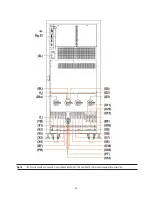
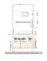
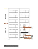
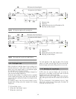
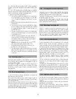
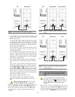
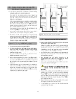
adding hardware. Fig. 27 and 28, as an example, show the circuit
diagrams of a three-phase input/three-phase output parallel system,
with and without separate static bypass line. Both circuit diagrams
are only showing the input-output power connections and the
parallel control BUS.
A part from the possible setting, conceptually, the parallel systems
are divided in two similar structures and at the same time very
different depending on the application.
Systems connected in parallel or active parallel, supply the loads
equally among them. Less when there is only one UPS, the system
will be able to be redundant or non-redundant depending on the
needs and requirements of the application.
•
Simple parallel system (non-redundant)
: a non-redundant
parallel system, is that one where all UPSs supply the required
power by the loads. Total power of the system based on N
equipments of nominal power rate Pn, is N x Pn.
If the system is operating with a load close or equal to the
maximum and one of them faults, the load will be shifted to
bypass automatically with make before break technique,
because it will not be able to support the consumption demand
due to the overload that it will be caused in the rest of UPSs.
•
Redundant system
: a redundant system is that one has one
or more UPSs than the minimum required by the total power of
the system (depending on the redundancy level), being the load
fair shared among them. So, the fault of any of them will cause
that the damaged UPS will be out of the system and the rest
will continue supplying the load with all the guarantees. Once
the damaged UPS is fixed, it can be connected to the system in
order to recover the redundant condition.
A system with his configuration increases the reliability and
assures an AC power supply of quality for the most critical
loads.
The quantity of redundant equipments to be connected has to
be studied according to the requirements of the application.
Parallel connection, redundant or not, adds several advantages
a part from the connection itself:
•
Higher punctual power and back up time
: in a parallel
system of N+M equipments, it is considered the nominal
maximum load of N equipments and +M are the reserve ones,
so:
N, is the quantity of equipments in parallel, corresponding to
the minimum quantity required by the total needed power.
+M, is the additional quantity of equipments corresponding
to the residual safety power (redundant equipments).
Although, in practice it can drain the total power in that the N+M
system can supply, the redundancy requirement or conception
does not advice it and in compensation there is a surplus of
dynamic power against load demands.
I.e., a redundant parallel system with 3 UPS of 40 kVA and N+1
configuration, the nominal maximum load contemplates 80 kVA
(2x40 kVA), although the system can accept load demands up
to 120 kVA (3x40 kVA).
Therefore, the fact of M reserve equipments, increases
the back up time of the set, because the battery set is higher.
•
Modularity
: capacity can be added to a UPS parallel system
by adding equipments of the same feature, without needing to
replace the equipments already installed.
I.e., if time later, an installation with a parallel system of 2 UPSs
is detected that the capacity of this system is not enough, it can
be opted for adding a third equipment to the system, without
replacing the 2 original equipments.
The UPS parallel system management of
UPS
series is done by a
MASTER-SLAVES protocol, where only one equipment (MASTER)
takes the control of the rest ones (SLAVES). So, the control of the
output voltage, bypass shifting, disconnections, mains
synchronisation, ...; are managed by the MASTER equipment, and
transmitted to the SLAVES equipments through the management
bus of the parallel system.
This MASTER or SLAVE condition is dynamic as it is described later
and it will depend on several factors (initial status of the
equipments, chronological order of commissioning or shutdown of
the system through one equipment or other one, ...)