


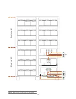


30
50 cm.
UPS battery
cabinet no 1
UPS battery
cabinet no 2
UPS cabinet
no 1
UPS cabinet
no 2
UPS cabinet
no 3
UPS cabinet
no 4
UPS battery
cabinet no 3
UPS battery
cabinet no 4
25 cm.
150 cm.
10 cm.
25 cm.
50 cm.
50 cm.
50 cm.
25 cm.
10 cm. 25 cm.
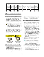
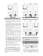
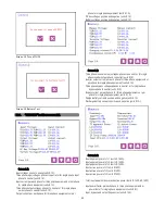
Fig. 30.
Floor view with minimum distances for a parallel system.
5.1.4.3. Equipment immobilized and levelled.
• All UPSs
and battery modules, which have casters, have 4
stabiliser elements
(PB)
, arranged next to each caster.
• The purpose of the stabilisers elements
(PB)
is lay, immobilize
and level the metallic cabinet once it has been located, in order
to avoid possible overturns, in particular those ones that battery
shelves can be extracted.
Warning!
Turnover danger when extracting the battery
shelves without stabilising the unit previously. Do not
extract more than one shelf at the same time, high risk
of causing serious injuries to the operators due to the
impact of the possible fall and/or trapping of the
equipment.
• Loosen the elements
(PB)
by hand turning them
counterclockwise as far it would go with the floor and with the
help of a spanner, loosen them half turn more in order to
immobilize the metallic cabinet, having a correct levelling.
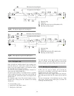
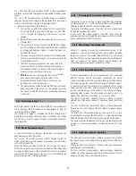
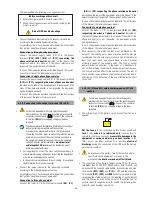
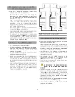
Fig. 31 shows how the stabilizers elements
(PB)
have to be
finally.
• To have access to the battery shelves, cabinet side covers have
to be removed and they have to be unblocked. Shelves can be
extracted through both sides and each one has a stopper.
5.1.4.4. Preliminary considerations before connecting.
• The description of this manual refers to the connection of terminals
and switching manoeuvring that are only available in some versions
or equipments with extended back up time. Ignore those
operations regarding them, if the unit does not have them.
• Follow and respect the instructions described in this section
referred to the installation of a single equipment or parallel system.
• Switchgear or external manual bypass panel boards:
It is advisable to have an external manual bypass panel
board equipped with input, output, static bypass (
UPS-B
version only) and manual bypass protections, in single
installations.
For parallel systems up to two units, it
is very advisable
having a switchgear panel board and for systems with 3 or
4 equipments,
it is essential
. Switches of the panel board
have to allow isolating the UPS from the system against any
wrong operating and feed the loads with the rest ones,
either during the preventive maintenance period or the
reparation of itself.
• Under request an external manual bypass panel board for a
single equipment or parallel system can be supplied.
Original position from factory
of the element
(PB)
.
Element
(PB)
tighten
against the floor.
•
If it’s required more detailed information for particular
system configuration, ask for the relating «Recommended
installation» information. In that information is shown the
circuit diagram, as well as the protection size and minimum
cross section of the wires that are connected to
Fig. 31.
Equipment / battery module stabilisers elements
(PB)
.
• Equipment maintenance and battery handling is a reserved task
to the
S.T.S.
or authorized staff.
If for any reason, the battery sliding shelves would need and
intervention, it is essential to pay attention and respect the
indications of the label sticked in each shelf, before
extracting them (see Fig. 31).
the equipment, taking into account the nominal operating voltage. All
figures are calculated for a
maximum total cable length of 30 m
between the distribution panel board, equipment and loads.
For longer lengths correct the cross sections accordingly, in
order to avoid dropping voltages, by respecting the Regulations
or norms corresponding to the country.
In manual and for each setting, the information is available