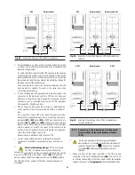


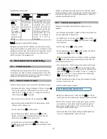


48
At this level an authorized password will be required to modify some
advanced parameters.
˙
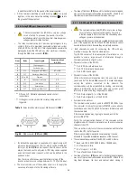
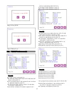
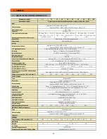
Screen 3.5: Rated Value Screen
Fig.47. Screen 3.5 «Rated Value».
To modify the rated values on the screens, it is necessary to
introduce the «Password» on the previous screen 3.4. otherwise, they
only will be able to be visualized.
The IP.V and OP.V shows the Rated Input Rectifier Voltage and Rated
Output Voltage..
It also shows Upper Margin and Input Rectifier Voltage Lower Margin
of the Input Rectifier Voltage and Input bypass voltage, The Rated DC
Bus Voltage and the Rated Output Current. The Rated Battery
Charging Current. And the probe for the battery and AC input current
˙
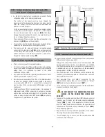
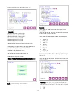
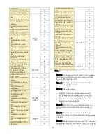
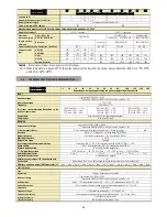
Screen 3.6: Information
In this Screen <<Information>> you can check the UPS
configuration of the unit
Configuration and status of the unit:
- «Single:» “Single” connection.
- «Parallel-Single» Parallel connection. Unit is on “single” state.
- «Parallel-Master» Parallel connection. Unit is on “master” state.
- «Parallel-Slave» Parallel connection. Unit is on “slave” state.
Internal firmware versions of both Digital Signal Processor (“DSP Ver:”)
and microcontroller (“uC Ver:”). In the sample screen, “ver. 3.2 a” and
“ver. 2.4 b” respectively.
UPS Serial Number, expressed with 10 characters. Possible
characters ranges are “0”-“9”, “A”-“Z” and also “ “ (blank space), “-“.
See sample screen.
And the Service Information set in the basic menu.
Screen 3.7
And the information of Rated Values set in the Rated Value Menu.
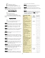
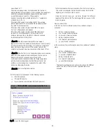
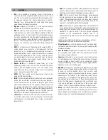
7.3.5. ‘‘Alarms’’ level (screen menu 4.0). See fig. 48.
When Alarm appears, in the Main Menu, you can only see one alarm,
but you can enter the Alarm Menu to check what are the alarms for
the unit currently as following:
Fig 48
Screen 4.0 «Alarms »
Figure 48 is showing just only some alarms as an example, but there
could be some of them, the active ones. In table 6, there are all the
possible alarms displayed in the display LCD.
˙
Alarm 1: This alarm indicates that the rectifier is overloaded. The
rectifier overload appears when the input current of any phase is
greater than the following ratio:
Iin-ovl = 0,326 x Pout / Vout_p-n