


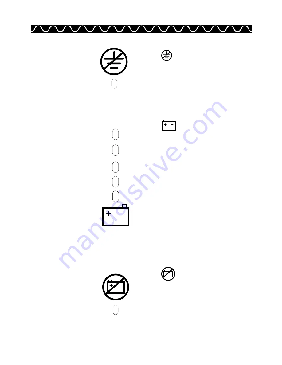
The red
Site Wiring Fault
LED will be on if
either the ground wire connection does not exist
or the line and neutral wires are reversed in the
line receptacle. This LED will stay on until the
condition is fixed. It is the customer’s responsibil-
ity to correct the wiring fault. The alarm can be
disabled by the customer using the dip switches
(see the Dip Switch Configuration tables in
Chapter 2).
The five
Battery
LEDs describe battery
conditions in the form of a bar graph.
Normal operation:
One or more of these LEDs
are on depending on the charge state.
Transfer to battery operation at AC Input fault:
As the battery capacity declines, the bar graph
reduces, with the LEDs turning off from top to
bottom.
Impending Low Battery:
the top four LEDs are
off and the bottom LED (red) is ON when there is
about 2 to 5 minutes of battery backup left.
Battery exhausted before line returns:
the
bottom LED (red) will flash for 10 minutes.
Line returns:
the bottom LED (red) turns off and
the remaining four green LEDs light up from
bottom to top as the batteries are charging. Once
fully charged, the LEDs will remain on unless
there are further problems.
The red
Battery Service
LED will be on
when a potential battery failure is detected. If
reset is pushed, this LED will continue to flash
until service is performed.
UPS Owner’s Manual
23
(green)
(green)
(green)
(green)
(red)
Battery
(red)
Site Wiring Fault
(red)
Battery Service
Содержание 0 ACE2200
Страница 1: ...THE ELECTRONIC SYSTEM POWER SPECIALISTS Uninterruptible Power System 400VA 2200VA ...
Страница 2: ...Part Number 05141270 Revision C 3 94 ...
Страница 11: ...Model ACE2200 Model ACE2000 UPS Owner s Manual 7 ...
Страница 24: ...Chapter 2 Installation 20 NOTES ...
Страница 36: ...Chapter 5 Specifications 32 NOTES ...
Страница 39: ...The remaining pages were left blank intentionally ...
Страница 40: ......