PowerFleet VAC4 Скачать руководство пользователя страница 44


PowerFleet

®


VAC4 and VAC4S Hardware User’s Guide


085-00000700 Rev K 

[email protected] 

Page 47 of 103 


The VAC will automatically download the configuration data associated with that vehicle ID and display one of the 
following messages:  

VAC Message 

Meaning 

Configured Success


The replacement VAC is successfully configured.  

Not All Configured 

Some configuration data is missing or different than the previous VAC (This is likely to occur if 
the replacement VAC has a newer firmware version than the VAC being replaced).  In this case, 
a Maintenance operator must manually configure the replacement VAC as if it was a new 

vehicle installation, using the VAC’s Install Wizard. Refer to PowerFleet® Installation Guide.


Wrong Version! 

The previous VAC had a significantly older version of firmware than the replacement VAC.  In 
this case, contact the local System Administrator or PowerFleet support team.  

VAC NOT FOUND 

The VAC ID is not found in the system database.  In this case, the vehicle ID should be double-

checked with the local System Administrator, and the “CloneVAC” process re

-run. Then the 

correct vehicle type and vehicle ID can be entered.  


Note:


If a VAC is moved from one vehicle to another vehicle, use the VAC’s Install Wizard, not the “CloneVAC” function

(See Section 2: Configuring the VAC).  
 

Checking VAC Synchronization Status 

For communication efficiency purposes, there are many VAC profile segments that can be updated and synchronized 
independently.  The Vision Pro software displays the synchronization status for all communicating vehicles. However, 
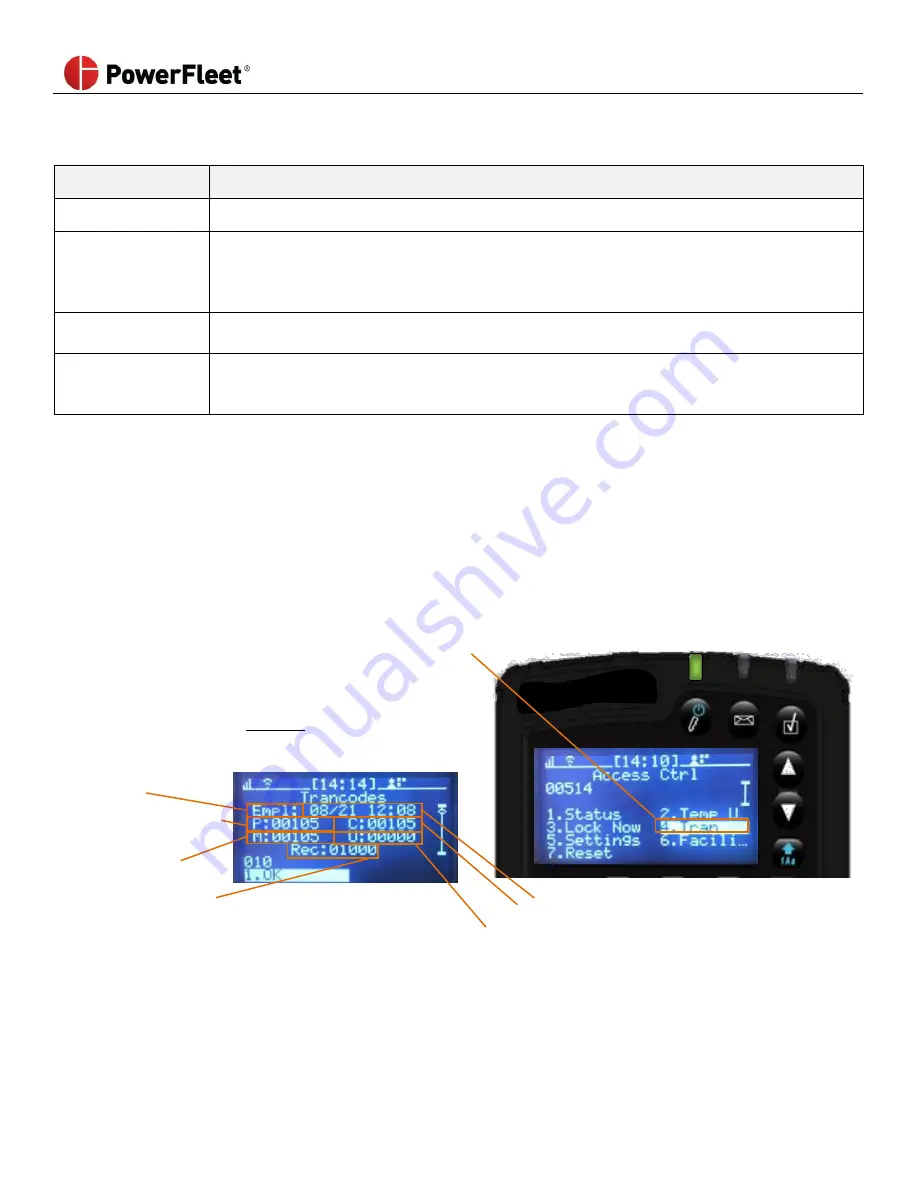
the following explains the content. On the VAC menu screen:  

1.


Select ACCESS.  

2.


Select TRAN, to 

check on a particular VAC’s synchronization status.


Incremental count when in range  
(always increments in range) 


Note:


If the “M” number is 

less than 

the “C” number, then 


the VAC’s segment is not updated. 


Profile segment name 


P


Pending version 

M


Latest version 
required 


Date and Time of last completed update  

Rec

  Records received for synchronizing segments 

C


Latest version on the VAC 


Version retained following a firmware upgrade 


Содержание VAC4

Страница 1: ...em VMS Hardware User s Guide An operating and troubleshooting guide for the VAC4 VAC4S WAM and other peripheral hardware some features require firmware from system release 08 05 00 or later 123 Tice B...

Страница 2: ...e completed by certified personnel ONLY using the proper tools and following the proper safety protocols The procedures and recommendations in this Guide do not supersede any Federal State or Local re...

Страница 3: ...ly using Intelligent RF IRF 24 Wirelessly using Wi Fi 24 IMPACT SENSOR CONFIGURATION 24 READING VAC INFO SCREENS 26 SECTION 3 STANDARD OPERATORS 28 LOGGING INTO THE VAC TO START THE VEHICLE 28 Login E...

Страница 4: ...Battery Voltage Monitoring 63 SECTION 6 WAM USE AND TROUBLESHOOTING 64 WAM Use 64 WAM LEDs Explained 64 WAM Troubleshooting 65 65 Multitech Modem LEDs Explained 65 Cradlepoint Modem LEDs Explained 66...

Страница 5: ...se Getting Started Guide General system instructions for the site coordinator PowerFleet Enterprise Installation Guide Installation instructions for vehicle hardware Cellular Wireless Asset Manager In...

Страница 6: ...n be accessed by the operator without interfering with any vehicle operation VAC interfaces with the vehicle for power ignition access control and usage monitoring using an 18 foot cable harness VAC i...

Страница 7: ...When the VAC is powered the VAC has three integrated LEDs for operator and supervisor status indication LED Message LED State Indication Access Off No one logged in and the vehicle is in Registered I...

Страница 8: ...he arrow pointed to the right is visible the VAC has not recently received data from the CAN such as when the key is off If only the arrow pointed to the left is visible communication with the CAN is...

Страница 9: ...ame countdown will also appear in the Status Header The vehicle has an active checklist that requires a Standard operator to complete Diagnostics The blinking Diagnostic icon is accompanied by a blink...

Страница 10: ...ls Master The Master icon is accompanied by a blinking yellow LED The vehicle has an active checklist that requires a Master or Maintenance operator to complete New Message The New Message icon is acc...

Страница 11: ...ating text and available responses Each section auto resizes based on the number of menu options Current selected response is highlighted ENTER key confirms the highlighted selection and advance to th...

Страница 12: ...ghted Left and Right ARROW keys move blinking cursor left or right Quick press ESC key exits to the previous screen Long press ESC key exits to the home screen Quick press ENTER key confirm the entere...

Страница 13: ...Header Scroll indicator vertical bar Up and Down ARROW keys scroll through available choices Returns to the top row when advancing past the last row Ordinal position of item currently highlighted 1st...

Страница 14: ...vided by the end user When the system is in Any ID access mode default configuration when the VAC is shipped an access ID creates a Place Holder operator profile in the PowerFleet Vision Pro software...

Страница 15: ...signed software access credentials If you do not know the facility ID contact PowerFleet s Support 3 Select vehicle type FR Forklift Rider OP Order Picker SE Sweeper TR Turret Truck FS Forklift Stand...

Страница 16: ...VAC using the keypad 1 Log into the VAC as a Maintenance operator or IT operator 2 From the VAC main menu screen Select Wi Fi 3 If the VAC is in range of wireless networks a list will appear on the V...

Страница 17: ...ally attempt to connect to the selected SSID using the credentials provided b If the VAC display does not list the desired SSID select OTHER Press ENTER i Using the VAC keypad manually enter the SSID...

Страница 18: ...ion range All Wi Fi profile components SSID credentials server IP port etc are transmitted VACs must be configured with the same facility code and RF frequency to successfully send and receive a trans...

Страница 19: ...s correct If the information needs to be updated click Edit on the bottom right frame of the window 6 Update Wi Fi Security credentials 7 Verify the correct Wi Fi security parameters are entered 8 Cli...

Страница 20: ...the current tran codes to the synched tran codes if they are the same the item has been synchronized To view the synchronization status of all vehicles a Select Reporting in the top right frame b Scro...

Страница 21: ...c and designed to work out of the box The first step is calibrating the impact sensor which relies on proper installation and mounting The purpose of the calibration is similar to resetting an empty s...

Страница 22: ...ill store and report event details about without taking any on vehicle actions Medium Impact The VAC will flash an LED and prompt the operator to complete a self inspection checklist to identify injur...

Страница 23: ...ronized D IRF frequency for VMS data R IRF data rate Sync Segment Quick Status one letter per segment Lowercase received NOT synchronized UPPERCASE synchronized see VAC Synchronization Status section...

Страница 24: ...AC can only program available firmware by a request from an authorized operator 09 19 29 39 49 59 69 79 89 99 C9 D9 VAC can only program available DB firmware 03 13 23 33 43 53 63 73 83 93 1B 2B 3B 4B...

Страница 25: ...or security Press ENTER 3 If the access ID is authorized for that vehicle the vehicle will start and the VAC s green LED will turn on If a safety checklist has not been completed for the vehicle withi...

Страница 26: ...ot authorized for use The vehicle is taken out of service via the system software or the vehicle does not belong to any group with valid authorization expiration A System Administrator can put the veh...

Страница 27: ...ypad operators The About display screen v Release version c Release year LP Troubleshooting information LE Troubleshooting information Opr Operator type LR Troubleshooting information Installed Firmwa...

Страница 28: ...essfully logs off a vehicle the vehicle will become deactivated the VAC s main login screen will reappear and the VAC s green LED will turn off Note The operator is responsible for the vehicle until h...

Страница 29: ...on the number of menu options Up and Down ARROW keys scroll through checklist questions if applicable Returns to top row when advancing past the last row Selected checklist current response highlighte...

Страница 30: ...cklist prior to completing all questions the VAC screen will ask if the operator wants to exit the checklist Exiting a checklist prior to completion will violate safety compliance requirements and res...

Страница 31: ...response the checklist is completed the operator is automatically logged off and the vehicle is locked out Note The vehicle will NOT lock out operators while in Any ID mode The VAC remains disabled fo...

Страница 32: ...n idle for a period of time The default time is 10 minutes When the idle timeout occurs a countdown appears on the VAC screen and the left LED alternately blinks green and orange to alert the operator...

Страница 33: ...ID mode and a countdown will begin High and Severe impacts safety checklist non compliance and checklist critical responses all result in vehicle lockouts and require Master or Maintenance operators t...

Страница 34: ...a Standard operator in the Receiving group needs to use a Shipping group vehicle a Master operator can temporarily authorize that operator on that vehicle The temporarily assigned operator does not h...

Страница 35: ...le to be temporarily assigned 2 On the first menu screen select the ACCESS 3 On the Access Ctrl sub menu select TEMP USERS 4 On the Temp Users sub menu select ADD USER 5 Touch the iButton fob Access I...

Страница 36: ...ACCESS 2 Select STATUS To clear a vehicle lock out and return the vehicle to operation a Master operator or a Maintenance operator must perform the following 1 Log into the locked vehicle The screen d...

Страница 37: ...te safety checklist countdown on a vehicle when the operator has a next log in perhaps in a case where maintenance inspected the vehicle adhoc perform the following 1 Log into the vehicle 2 On the fir...

Страница 38: ...When a vehicle is locked only a Master operator or a Maintenance operator can access and use that vehicle To lock a vehicle a Master or Maintenance operator must perform the following 1 Log into the v...

Страница 39: ...when a VAC is replaced Maintenance operators should not enter the Install menu unless they need to re configure the VAC See Section 2 Configuring the VAC for more details on VAC configuration VAC Tim...

Страница 40: ...is not operating properly When an error is active the RED LED blinks and the screen displays a blinking error icon See Section 7 VAC Troubleshooting for details on the error definitions and troublesh...

Страница 41: ...sub menu one of the following three menu options Selecting ID OPTIONAL will put the vehicle into soft bypass operators will NOT be required to log in to use the vehicle though operators may log in if...

Страница 42: ...ftware Determining the credentials of an ID is most commonly performed when an ID is found without an operator to claim ownership 1 Log into the vehicle 2 On the first menu screen select HARDWARE 3 On...

Страница 43: ...umber IMPORTANT When replacing an existing VAC DO NOT use the VAC s Install Wizard After connecting a replacement VAC to an existing VAC cable the VAC screen will display an error message when it powe...

Страница 44: ...in the system database In this case the vehicle ID should be double checked with the local System Administrator and the CloneVAC process re run Then the correct vehicle type and vehicle ID can be ente...

Страница 45: ...c are added deleted or updated in Vision Pro software Prof P Profile This segment increments when any of the vehicle s sensor configuration idle sleeper power down GPS etc is edited in Vision Pro soft...

Страница 46: ...ation range Note When the VAC is within wireless communication range of a facility ID different than the one entered during configuration diagnostic error 25 will appear on the VAC display screen Forc...

Страница 47: ...database to resume normal operation There is a diagnostic error code that displays when the backup battery has a low charge However if you want to proactively check a battery to ensure it is charging...

Страница 48: ...ub menu to change the RF communication frequency select MyFreq D Data Frequency iRF VAC data transmission L Location Frequency iRF uses to determine VAC location R Data Rate iRF data speed setting Mai...

Страница 49: ...Guide 085 00000700 Rev K support powerfleet com Page 52 of 103 Checking and Changing the VAC Usage Totals Maintenance operator must perform the following 1 Log into the vehicle 2 Select HARDWARE 3 On...

Страница 50: ...ve voltage signals To be sure the BLU wire connection will work for the Install Wizard there is a MotionTest screen available to see the VAC results in either of these modes Connect the BLU wire using...

Страница 51: ...may be identical 1 Log into the vehicle 2 On the first menu screen select HARDWARE 3 Scroll down to the second page of the menu screen 4 On the Hardware sub menu select MOTION Idle or Motion Current m...

Страница 52: ...Current value evaluated versus engine off ranges to determine engine state Idle or EngOn Current engine state Idle Engine off EngOn Idling Th1 Threshold above and below Id1 center point that equals t...

Страница 53: ...CHANGING SETTINGS AV Current value evaluated versus idling ranges to determine vehicle state R Raw value currently being measured by sensor Th1 Threshold above and below Id1 center point that equals...

Страница 54: ...tain all of the following 1 Log into the vehicle 2 On the first menu screen select HARDWARE 3 On the Hardware sub menu select STATES 4 Values auto update to the most current reading 5 Select PAUSE to...

Страница 55: ...X DlyT Tow meter 0 1 or X Batt Current vehicle battery voltage B wire 0 99 9 volts Im X Y P Current impact sensor X axis Y axis and duration thresholds 0 255 Creeper CAN Serial mode that activates uns...

Страница 56: ...X X 02004 X X 04002 X X 04004 X X 0000A X X 0000B X X X 0000C X X 0001A X X X 0001C X X X 0008A X X X 0008C X X X 0009A X X X X 0009C X X X X 0200A X X X 0200C X X X 0400A X X X 0400C X X X The curre...

Страница 57: ...sReport The InsReport on the VAC screen display provides the detail of the last completed configuration parameter 1 Select HARDWARE IC vehicle Electric vehicle 1 Select InsReport VacID Vac Identificat...

Страница 58: ...ire GAS IC vehicles inactive 2nd set point and range SSSS RRR Lift Idle1 Lift motor BRN wire electric vehicles inactive 1st set point and range SSSS RRR Lift Idle2 Lift motor BRN wire electric vehicle...

Страница 59: ...sues are identified manual troubleshooting may be required Note A properly mounted and secured impact sensor is the most important factor in ensuring a working impact management system Reading the Imp...

Страница 60: ...ange to 00 0g or 00 1g to indicate a valid calibration Note Selecting UPDATE will update the current reading display without recalibration 5 Select OK when the calibration is acceptable Note The Toggl...

Страница 61: ...uld always be on except during a facility blackout A yellow light means the unit is in sleep mode EthLink Amber Ethernet port is connected This light should always be on EthActivity Green Blinks when...

Страница 62: ...the F1 light remains blinking contact IDSY Support F2 LED on Make sure the cable between the WAM and network or modem works For cellular WAMs if the Modem CD and at least 1 signal light are on and the...

Страница 63: ...ug the end that plugs into modem for power o If no power is present follow RMA procedures for the power adapter o If power is present reconnect to the modem power input and re check PWR LED status CD...

Страница 64: ...N position See Section 2 Logging onto the VAC Vehicle battery NOT connected Check that the vehicle battery is connected Check the voltage level on the 1 B and 9 B pins of the VAC to vehicle cable Inli...

Страница 65: ...fy Sensor Hub LED is blinking RED AMBER GREEN repeatedly Replace the Sensor Hub VAC is not properly powering the Sensor Hub If Sensor Hub LED is NOT lit Remove the Sensor Hub cable from VAC C102 port...

Страница 66: ...s the VAC screen will also display call Maintenance Only Maintenance operators can log into a VAC when a Shutdown error occurs FUNCTIONAL errors can limit system effectiveness and skew data Such error...

Страница 67: ...00 Error Msg 24 Hours Refer to Hardware Guide Error number Error cause Where to go for error resolution Error Codes 00 Error Msg 24Hrs Refer to Hardware Guide FUNCTIONAL Appears after a reference erro...

Страница 68: ...ire Note An open or zero reading indicates a damaged cable Replace the cable as needed and retest 09 Motion w o Login Refer to Hardware Guide FUNCTIONAL The VAC sensed motion while no one was logged i...

Страница 69: ...Motion Manually Adjust values as needed Vehicle cable Use an ohmmeter to check resistance check to verify cable integrity on the BLU wire Note An open or zero reading indicates a damaged cable Replac...

Страница 70: ...o Only the VAC should be returned for analysis repair o Once VAC is removed the system MUST be hard bypassed to use vehicle Follow instructions on how to hard bypass the system See Appendix B Faulty i...

Страница 71: ...m MUST be hard bypassed to use vehicle Follow instructions on how to hard bypass the system See Appendix B Run CloneVAC on the new VAC See Section 4 for instructions 18 Low Internal Batt Power VAC for...

Страница 72: ...for an RMA number o Only the Impact Sensor should be returned for analysis repair 20 Keypad PIC Err Contact IDSY FUNCTIONAL The VAC has detected an internal error Possible Cause s Action Internal VAC...

Страница 73: ...n RMA Request form See Appendix A Call PowerFleet s Customer Service for an RMA number Only the VAC should be returned for analysis repair Once VAC is removed the system MUST be hard bypassed to use v...

Страница 74: ...WAM and Modem LEDs match the recommended state Refer to the Cellular WAM Installation Guide If the LEDs do not match the recommended state reboot the WAM by unplugging the WAM waiting 30 seconds and...

Страница 75: ...se vehicle o Follow instructions on how to hard bypass the system See Appendix B o Run CloneVAC on the new VAC See Section 4 for instructions WAM Modem communication Verify that the WAM and Modem LEDs...

Страница 76: ...o Hardware Guide SHUTDOWN The VAC did not correctly detect forward motion during the configuration wizard phase when asked to move the vehicle forward for three second Possible Cause s Action Speeding...

Страница 77: ...e for the BLU wire is not blown or missing Repair as needed Log in to the VAC as a Maintenance operator and re run the configuration wizard see Section 2 BRN wire connection point Internal combustion...

Страница 78: ...n values see Defining Motion Manually Adjust values as needed Vehicle cable Use an ohmmeter to check resistance to verify cable integrity an open or zero reading indicates a damaged cable on the BLU w...

Страница 79: ...ehicles are connected to a circuit that will inhibit the vehicle from moving or shut the vehicle down for internal combustion vehicles when you are not logged into the VAC Refer to the PowerFleet Inst...

Страница 80: ...blown or missing Repair as needed Log in to the VAC as a Maintenance operator and re run the configuration wizard see Section 2 BRN wire connection point Internal combustion vehicles only Verify that...

Страница 81: ...te an RMA Request form See Appendix A Mounting using screws or non IDSY provided tape Re mount using provided tape Make sure that no other object is bouncing on top of sensor during normal driving Mak...

Страница 82: ...d into the VAC See the PowerFleet Installation Guide for recommended connection points 39 Forkload Config Er See Hardware Guide FUNCTIONAL The forkload sensor has not been calibrated successfully Poss...

Страница 83: ...onnector and connecting a voltmeter to pin 1 positive and pin 8 negative on C103 of the VAC The image at right shows how to read the pin layout and direction You must have 5 5 0 5 volts DC If the VAC...

Страница 84: ...See Appendix A o Call PowerFleet s Customer Service for an RMA number o Only the VAC should be returned for analysis repair o Once VAC is removed the system MUST be hard bypassed to use vehicle Follo...

Страница 85: ...s the system See Appendix B Run CloneVAC on the new VAC see Section 4 for instructions 47 Facility Code Error Refer to Hardware Guide FUNCTIONAL The facility ID entered in the VAC does not match the f...

Страница 86: ...t form refer to Appendix A in this document Call PowerFleet s Customer Service for an RMA number Only the VAC should be returned for analysis repair Once VAC is removed system MUST be hard bypassed to...

Страница 87: ...d be considered an issue Possible Cause s Action One time VAC issue None for Operators The VAC self re boots until the error is cleared Intermittent or continuous VAC issue Complete an RMA Request for...

Страница 88: ...returned for analysis repair o Once VAC is removed system MUST be hard bypassed to use vehicle o Follow instructions on how to hard bypass the system See Appendix B Run CloneVAC on the new VAC See Sec...

Страница 89: ...emoved system MUST be hard bypassed to use vehicle o Follow instructions on how to hard bypass the system See Appendix B Run CloneVAC on the new VAC See Section 4 for instructions WAM Modem communicat...

Страница 90: ...at sensor is working using the Hardware Impact screen X Y readings should be 0 0 0 2G with R readings between 70 and 90 on both axes If not sensor may be malfunctioning Malfunctioning impact sensor If...

Страница 91: ...36 Volt Source mA 12 80 100 25 140 200 48 60 or 72 Volt Source mA 10 55 80 20 100 140 Access Control Interface VAC4S VAC4 Min Nominal Max Min Nominal Max Output Voltage VDC coil connection 9 12 12 11...

Страница 92: ...EU Antenna Internal PCB antenna omni directional Depends on channel utilized Wi Fi Protocols supported 802 11 a b g n Frequency GHz 2 412 2 484 GHz 5 18 5 32 GHz 5 5 5 825 GHz Channels US 1 11 EU 1 13...

Страница 93: ...Mounting method 2 x M6 screws or bolts supplied Mounting holes 2 x dia holes for bracket 1x 1 25 dia round hole for cable Sensor Specifications Motion Sensing wired Specification Electric vehicle conn...

Страница 94: ...9 17 v3 1 1 2016 EN300220 1 2 v3 1 1 2017 EN300330 v2 1 1 2017 EN300328 v2 1 1 2016 EN301893 v2 1 1 2017 EN55032 2012 EN55024 2010 ETSI EN 300 489 1 3 EN 300 220 1 EN 300 328 EMC 2014 30 EU RED 2014 5...

Страница 95: ...re III IP67 Vibration MIL STD 810F Method 514 5 12 35Grms random vibration heavy duty truck chassis mount Shock MIL STD 810F Method 516 5 Procedure I 20 G Functional V 40 G Crash Hazard Drop product 3...

Страница 96: ...ocating Part Numbers on the next page Device Serial Number Description of failure primary symptoms or issue Shipment information address and contact details PO Approver in the event there is hardware...

Страница 97: ...Dealer or Customer Dealer Customer 2 Is the hardware shipped back to a Dealer or Customer Dealer Customer 3 Do you have a copy of the Hardware User Guide s Yes No 4 Did you call PowerFleet Support pr...

Страница 98: ...ons a Remove any wires connected to the orange wires of the access control relay and connect those wires to each other b Remove any wires connected to the grey wires of the access control relay and co...

Страница 99: ...ort or IP address is being blocked If the Wi Fi Test Failed contact your system administrator for support to connect to Wi Fi network PC BASED TEST TOOL 1 Download the IDSY Hosted WiFi Test Tool_v1 0...

Страница 100: ...completed test screen other than the above indicates the test was unsuccessful and there is an issue with the integrity of the connection to the server IT should verify the AP logs firewalls etc to co...

Отзывы: