9
Scroll Enclosure Air Compressors
Items
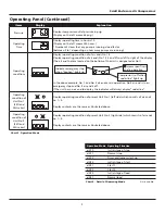
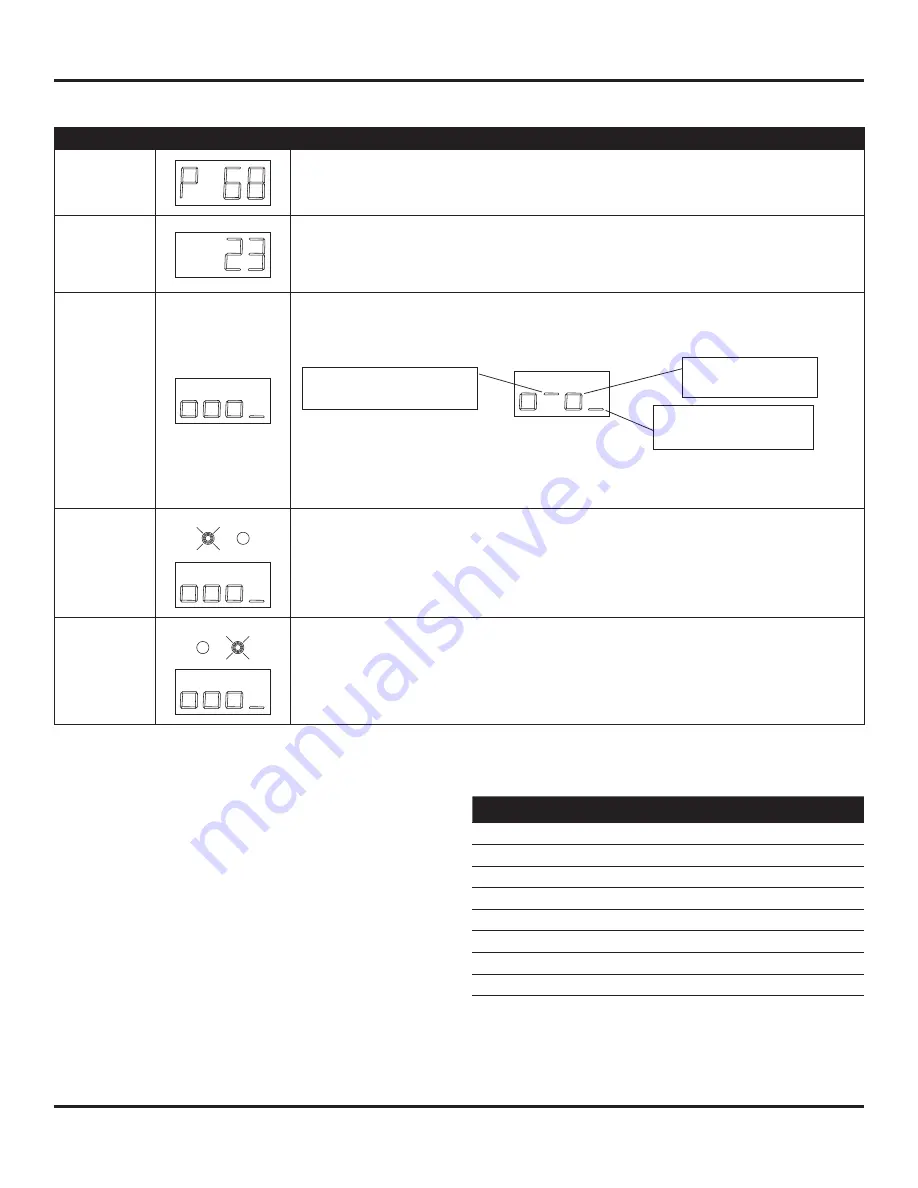
Display
Explanation
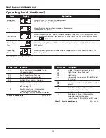
Pressure
Displays compressor outlet pressure in psig
(Display on the left means 68 psig.)
Operating
Time
Displays operating time in hours x10.
(Display on the left means 230 hours.)
* Number of Hours that any pump is running x load factor
(between 0 to 1 depending on how many pumps are running)
Operating
conditions
Displays operating condition of of air ends No. 1-4
Displays operating condition of air ends No. 1,2,3 and 4 from left to right of the display
(The air end that are located on the bottom of the Unit is designated as No 1)
In the above example, No. 1 and No. 3 air ends are in operation, No.2 air end is in an
emergency stop and No. 4 air end is off.
If the unit has no air end to display, the indicator will always display “underline”.
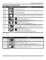
Operating
condition of
Unit No. 1
(SEO and
SEH series)
Displays operating condition of present Unit No. 1 (left side) which consists of air ends
no. 1~4.
Display contents are the same as illustrated above.
Operating
condition of
Unit No. 2
(SEO and
SEH series)
Displays operating condition of present Unit No. 2 (right side) which consists of air ends
no. 1~4.
Display contents are the same as illustrated above.
Chart 3 - Operation Mode
●
means specifi c air
end in operation
Compressor is off when
“underline” lights up
Indicates emergency stop
when “hyphen” lights up.
Operating Panel (Continued)
Operation Mode
Operating Situation
dX10
Initial stage of stop
dX11
Normal stop
dX12
Dryer preliminary start-up
dX20
Initial stage of start
dX21
Start 1
dX22
Start 2
dX30
Initial stage of load
dX31
Normal load
Chart 4 - Detail of Operating Mode
X: Air end No.


