5
Scroll Enclosure Air Compressors
Installation (Continued)
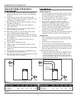
2) Install the exhaust duct in order to minimize the
pressure lost of the ducting. Keep the distance between
the inlet duct and the compressor exhaust to be at least
12 inches for ease of maintenance. Intake section of the
duct should be larger than the dimension of compressor
exhaust shown below:
WIRING
All electrical hook-ups must be performed by a qualifi ed
electrician. Installations must be in accordance with local and
national electrical codes.
1. Use solderless terminals to connect the electric power
source.
2. Remove front panel.
3. Remove the rectangle electrical box cover located
beneath air inlet fi lter on the right front of the unit.
4. Connect the power inlet cable to the inlet power
junction block located on the inlet side of all starter
connections.
Consult your NEC and local codes for wire size
PIPING
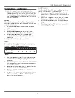
These units do not include air receivers. An air receiver can
be purchased separately. Please consult our distributors. Use
Chart 2 as a guideline for sizing the air receiver.
1. Make sure the piping is lined up without being strained
or twisted when assembling the piping for the scroll
compressor.
2. Appropriate expansion loops or bends should be installed
at the compressor to avoid stresses caused by changes in
hot and cold conditions.
3. Piping supports should be anchored separately from the
compressor to reduce noise and vibration.
4. Never use any piping smaller than the compressor
connection.
5. Use
fl exible hose to connect the outlet of the compressor
to the piping so that the vibration of the compressor
does not transfer to the piping.
SAFETY VALVES
The fl ow capacity of a safety valve should be equal to or
greater than the capacity of the compressor.
1. The pressure setting of the safety valve must not be
greater than the maximum working pressure of the air
receiver.
2. Safety valves should be placed ahead of any possible
blockage point in the system, i.e. shutoff valve.
3. Avoid connecting the safety valve with any tubing or
piping.
4. Manually operate the safety valve every six months to
avoid sticking or freezing.
Model
10 HP
15 HP
20 HP
30 HP
40 HP
Air Receiver Minimum
Capacity (gallons)
30
60
60
110
160
Chart 2


