Med Touch Series LCD Alarm Systems
Powerex
•
150 Production Drive
•
Harrison, OH 45030
•
USA
P 1.888.769.7979
•
F 513.367.3125
•
www.powerexinc.com
IN597400AV
•
08/2016
Page 21 of 56
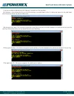
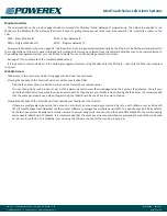
Programming the Gas Service (Area Alarm)
After placing the board in the program mode and touching the GAS
function icon, the gas input screen (shown here) is displayed. The
alarm panel has been pre-programmed with the gas service desired
based on the part number which was
ordered. To select a different gas service
use the double arrow left or right
buttons to scroll thru the database of
gas services until you find the one you
need
• then touch Enter
• on the next screen touch Back
• on the next screen touch Save
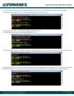
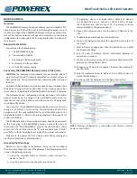
Programming Language and Latching or Non-latching Alarm
Relays
After placing the board in the program
mode and touching the Set function
icon, the sets input screen (shown here)
is displayed. The alarm panel has been
pre-programmed with the language
desired based on the part number
which was ordered. Choose a different
language set by simply touching the
button you would like. Your selection
will take you immediately to the next
screen on which you should touch Back
and on the next screen touch Save. You
will need to re-enter the program mode and again select the Set
function icon to choose Latching (LATCH) or Non-Latching (NLATCH)
software. Your selection will take you immediately to the next screen
on which you should touch Back and on the next screen touch Save.
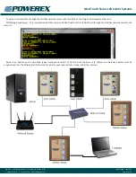
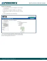
View Screen
After placing the board in the program
mode and touching the VIEW function
icon, the view screen (shown here) is
displayed. The view screen provides a
summary view of all of the programming
for the circuit board. It does not provide
any programming options. It is simply a
view only screen. The first line provides
the software version. The Cal value
represents any re-programmed change
from the factory calibration. The High
and Low Limit values are the high and
low pressure alarm set points. The Units
value is the units of measure. The Repeat value is the number of
minutes in which an alarm will be repeated after it has been silenced
but remaining in an alarm condition. The Gas Type number is a code
(see table below) which corresponds to the gas service which has been
programmed for the board. The Com ID number is the communication
ID number which has been programmed for the board. The Language
Set is an abbreviation for the label set which has been programmed
for the board. The Alarm Logic is the latching or non-latching software
which has been programmed for the board. MSG 1 are the rooms or
area(s) covered by the alarm. MSG 2 are the emergency instructions
programmed for the board.
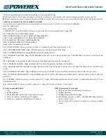
The gas boards are pre-programmed for a specific gas service
from the factory. After placing a gas board in the program mode, it
is possible to change the gas service of the board. It is an NFPA 99
requirement that the transducer gas service match the gas service
of the gas board to which it is connected. The following list cross
references the number that is actually displayed on the gas board
numeric display with the full names of the gases:
Gas # Displayed
Gas Service
Transducer Type
12
Nitrogen
250
24
Oxygen
100
04
Nitrous Oxide
100
08
CO
2
or CO
2
-O
2
Mix
100
22
Medical Vacuum
30
32
WAGD/AGSS
30
16
Medical Air
100
06
Helium or Heliox
100
H16
Instrument Air
250
H24
Hyperbaric Oxygen
100
H08
Medium Pressue CO
2
100
SP
Gas Mixture
100
HSP
High Pressure Gas Mix
250
3SP
Tri-Gas
100


