background image

17 


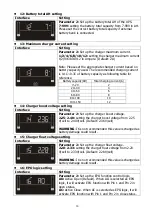
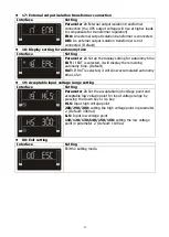
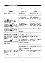
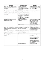
There are two parameters to set up the UPS.   

Parameter 1: Setting ID. Refer to below table. 
Parameter 2: Options values for each setting. 


01: Output voltage setting 

Interface 

Setting 


Parameter 3: Output voltage 

You may choose the following output voltage: 

200:

 presents output voltage is 200Vac 

208:

 presents output voltage is 208Vac 

220:

 presents output voltage is 220Vac 

230:

 presents output voltage is 230Vac (Default) 

240:

 presents output voltage is 240Vac 


02: Frequency Converter enable/disable 

Interface 

Setting 


Parameter 2: 

Enable or disable converter mode. You may 

choose the following two options:


CF ENA: 

converter mode enable 

CF DIS: 

converter mode disable (Default) 


03: Output frequency setting 

Interface 

Setting 


Parameter 2: Output frequency setting.   

You may set the initial frequency on battery mode: 

BAT 50:

 presents output frequency is 50Hz 

BAT 60:

 presents output frequency is 60Hz 

If converter mode is enabled, you may choose the following 
output frequency: 

CF 50: 

presents output frequency is 50Hz 

CF 60: 

presents output frequency is 60Hz 


04: ECO enable/disable 

Interface 

Setting 


Parameter 2: 

Enable or disable ECO function. You may 

choose the following two options:   

ENA:

 ECO mode enable 

DIS: 

ECO mode disable (Default) 

4.5.


UPS Setting 

Содержание VFI1000QS

Страница 1: ...VFI1000QS Online Double Conversion Silent UPS System Version 1 0 User Manual...

Страница 2: ...on 6 3 5 Tower Installation 7 3 6 UPS Location 7 3 7 UPS Connections 8 3 8 Starting Up the VFI1000QS 10 3 9 Start up on battery cold start 10 3 10 Switching off the UPS 10 3 11 Install software Option...

Страница 3: ...let which should be easily accessible and close to the UPS system Use supplied input mains cord Please use only BS Kite marked VDE tested and or CE marked power cables to connect the loads to the UPS...

Страница 4: ...mutilate batteries Released electrolyte is harmful to the skin and eyes It may be toxic Batteries may cause electric shock and have a high short circuit current Please take the precautionary measures...

Страница 5: ...voltage window Noise Transients Harmonics Distortions on the input mains voltage are not transferred to the load The load is powered from the UPS inverter at all times which is ReGenerating a new AC...

Страница 6: ...o the DC bus voltage to feed the inverter when running on battery operation The inverter converts the DC bus voltage into the AC output voltage It is a high frequency highly efficient design that util...

Страница 7: ...Be sure that nothing inside the package is damaged Please keep the original packaging in a safe place for future use For safety the UPS is shipped out from the factory without connecting the battery...

Страница 8: ...lation to position this UPS Step 1 Step 2 Fit the rack ears observing left marked L and right marked R positions when looking at the unit When in a rack the VFI1000QS must be supported by a shelf or r...

Страница 9: ...15 C to 25 C for optimal operation For every 2 C above 30 C the UPS will need to be derated by 10 of nominal capacity at full load The highest working temperature requirement for UPS operation is 40 C...

Страница 10: ...ver current protection in place not exceeding 16A e g a circuit breaker Note Check if the site wiring fault indicator lights up in LCD panel It will be illuminated when the UPS is plugged into an impr...

Страница 11: ...the card is properly located within the grooves in the housing before attempting to fully engage 3 7 5 Network connection Network Fax Phone surge port Connect a single modem phone fax line into surge...

Страница 12: ...ton for at least 2 seconds to turn off the UPS 2 The UPS will enter standby or bypass mode if AC power is present or switch off if switched off when in battery mode For optimal computer system protect...

Страница 13: ...es Note Upon battery disconnection equipment is not protected from power outages Step 1 Step 2 Step 3 Remove front panel Disconnect battery wires Pull out the battery box by removing two screws on the...

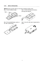
Страница 14: ...inside of UPS Step 1 Remove adhesive tapes Step 2 Connect all battery terminals by following below diagram Step 3 Put assembled battery packs on one side of plastic shells Step 4 Cover the other side...

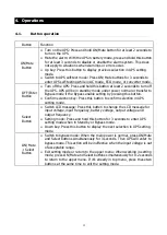
Страница 15: ...ction key Press this button to confirm selection in UPS setting mode Select Button Switch LCD message Press this button to change the LCD message for input voltage input frequency battery voltage outp...

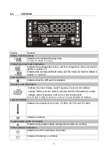
Страница 16: ...abled Output Load information Indicate the input voltage input frequency input current battery voltage battery current battery capacity ambient temperature output voltage output frequency load current...

Страница 17: ...tery level by 0 24 25 49 50 74 and 75 100 Indicates low battery Battery Mode Sounding every 5 seconds Low Battery Sounding every 2 seconds Overload Sounding every second Fault Continuously sounding By...

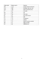
Страница 18: ...OIT Output isolation transformer EAT Estimated autonomy time RAT Running autonomy time CF Converter ON ON SD Shut down OI Over input current EP EPO TP Temperature CH Charger FU Bypass frequency unsta...

Страница 19: ...meter 2 Enable or disable converter mode You may choose the following two options CF ENA converter mode enable CF DIS converter mode disable Default 03 Output frequency setting Interface Setting Param...

Страница 20: ...fault 12V 06 Bypass enable disable when UPS is off Interface Setting Parameter 2 Enable or disable Bypass function You may choose the following two options ENA Bypass enable DIS Bypass disable Default...

Страница 21: ...low loss point from 55Hz to 59Hz Default 57 0Hz 09 Programmable outlets enable disable Interface Setting Parameter 2 Enable or disable programmable outlets ENA Programmable outlets enable DIS Programm...

Страница 22: ...00 10 100 150 12 14 Charger boost voltage setting Interface Setting Parameter 2 Set up the charger boost voltage 2 25 2 40 setting the charger boost voltage from 2 25 V cell to 2 40V cell Default 2 36...

Страница 23: ...tting for autonomy time EAT If EAT is selected it will display the remaining autonomy time Default RAT If RAT is selected it will show accumulated autonomy time so far 19 Acceptable input voltage rang...

Страница 24: ...S can be set at a constant output frequency 50 Hz or 60 Hz The UPS will still charge battery under this mode Battery mode When the input voltage is beyond the acceptable range or power failure the UPS...

Страница 25: ...ng 2 beep every 10 seconds Battery is not connected Over Charge Sounding every 2 seconds Site wiring fault Sounding every 2 seconds EPO enable Sounding every 2 seconds Over temperature Sounding every...

Страница 26: ...onnected Check if all batteries are connected well Fault code is shown as 27 on LCD display and alarm is continuously sounding Battery voltage is too high or the charger is fault Contact your dealer F...

Страница 27: ...fully charged Charge the batteries for at least 5 hours and then check capacity If the problem still persists consult your dealer Batteries defect Contact your dealer to replace the battery Fault cod...

Страница 28: ...operation Batteries are specified for 200 cycles Stored or remained off charge in a depleted state Be sure to deliver the spent battery to a recycling facility or ship it to your dealer in the replac...

Страница 29: ...ttery ECO Mode 96 full charged battery Battery Mode 88 BATTERY Battery Type 12V 9AH Numbers 4 Recharge Time 3 hours recover to 95 capacity for internal battery 2A charging current Charging Current 200...

Страница 30: ...V Capacity 18Ah Dimensions DxWxH mm 480 x 438 x 88 Net Weight kgs 29 Advanced Speed Control ASC Specification Fan Qty 2 Type PWM Controlled 80mm Minimum RPM 450 Maximum RPM 2200 Noise Output Minimum 1...

Страница 31: ...TY WILL ARISE OUT OF PI RENDERING OF TECHNICAL OR OTHER ADVICE OR SERVICE IN CONNECTION WITH THE PRODUCTS THE FOREGOING WARRANTIES AND REMEDIES ARE EXCLUSIVE AND IN LIEU OF ALL OTHER WARRANTIES AND RE...

Отзывы: