Power-Flo Pumps & Systems • 877-24PUMPS • www.powerflopumps.com
5
Minimum
Submergence Level
Bottom of Feet
9” for HTCE
Receiving Inspection
Upon receiving the pump, it should be
inspected for damage or shortages.
If damage has occurred, file a claim
immediately with the company that
delivered the pump. If the manual is
removed from the packaging, do not
lose or misplace.
Storage
Any product that is stored for a period
longer than six (6) months from the
date of purchase should be bench
tested prior to installation. A bench
test consists of, checking the impeller
to assure it is free turning and a run
test to assure the motor (and switch
if provided) operate properly. Do not
pump out of liquid.
Controls
Manual models require a separate
approved pump control device or panel
for automatic operation. Be sure the
electrical specification of the control
selected properly match the electrical
specifications of the pump.
Submergence
The pump should always be operated in
the submerged condition. The minimum
sump liquid level should never be less than
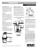
above the pump’s volute (See Figure 1).
Liquid Level Controls
Typical Discharge Pipe Mounted:
Refer to Figure 2 below which shows a
typical installation of a 1 phase 115 volt
pump using a level control mounted
to the pump with a piggy-back plug.
The level control should have adequate
clearance so it cannot hang up in it’s
swing and that the pump is completely
submerged when the level control is in
the “Off” mode. By adjusting the cord
tether the control level can be changed.
Automatic:
Plug float cord into GFI outlet, then
plug pump cord into float cord.
Manual:
Plug pump cord directly into GFI
outlet.
Level Control Basic Instructions:
Plug the level control plug into the GFI
receptacle, then plug the pump into the
piggy-back plug (See Figure 3). One cycle
of operation should be observed, so that
any potential problems can be corrected.
It is recommended that the level control
float should be set to insure that the liquid
in the sump never drops below the top
of the motor housing or a minimum level
of 6 inches (9inches on HTCE) above the
basin floor.
Installation
These pumps are recommended for
use in a sump or basin. The sump
or basin shall be sealed and vented
in accordance with local plumbing
codes.
This pump is designed to pump
effluent or wastewater, nonexplosive
and noncorrosive liquids and shall
NOT be installed in locations classified
as hazardous in accordance with the
National Electrical Code (NEC) ANSI/
NFPA 70 or Canadian Electric Code
(CEC).
The pump should never be
installed in a trench, ditch, or hole with
a dirt bottom. The legs will sink into
the dirt and the suction will become
plugged.
Figure 1
Receiving & Installation
Recommended
Submergence Level
Typical Installation with Wide Angle
Level Control
Figure 2
Figure 3
PFS411HTCE-2
Submersible Effluent, Sump & Sewage Pumps


