POWER ELECTRONICS
DB SERIES
INSTALLATION OF DYNAMIC BRAKING UNIT
19
TERMINAL
DESCRIPTION
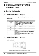
G Ground
terminal.
Connection for negative terminal of DC Bus of the drive
(DC Bus (-)).
N
Connection for B2 terminal of the dynamic braking
resistor.
B2
Connection for B1 terminal of the dynamic braking
resistor.
P / B1
Connection for positive terminal of DC Bus of the drive
(DC Bus (+)).
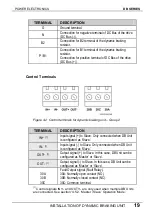
Control Terminals
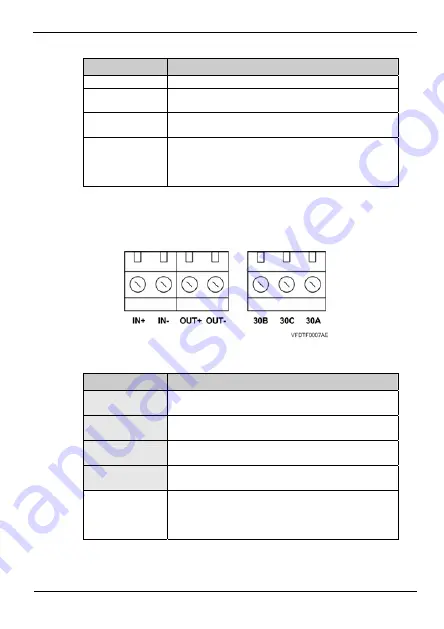
Figure 4.2 Control terminals for dynamic braking unit – Group 2
TERMINAL
DESCRIPTION
Input signal (+) to Slave. Only connected when DB Unit
is configured as ‘Slave’.
IN+
[1]
Input signal (-) to Slave. Only connected when DB Unit
is configured as ‘Slave’.
IN-
[1]
Output signal (+) to Slave. In this case, DB Unit can be
configured as ‘Master’ or ‘Slave’.
OUT+
[1]
Output signal (-) to Slave. In this case, DB Unit can be
configured as ‘Master’ or ‘Slave’.
OUT-
[1]
Fault Output signal (Fault Relay).
30A
30A: Normally open contact (NO).
30B
30B: Normally closed contact (NC).
30C
30C: Common terminal.
[1]
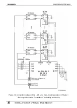
Control signals IN+/- and OUT+/- are only used when multiple DB Units
are connected. See section ‘4.5.2. ‘Master / Slave’ Operation Mode’.
Содержание SDRIVE DB Series
Страница 1: ...DB Series SDRIVE S D Y N A M I C B R A K I N G dynamic braking unit Getting Started Manual...
Страница 2: ...dynamic braking unit Getting Started Manual Edition October 2007 VFDF01AI Rev A...
Страница 3: ...DB SERIES POWER ELECTRONICS 2...
Страница 5: ...DB SERIES POWER ELECTRONICS 4...
Страница 7: ...DB SERIES POWER ELECTRONICS 6 INDEX...
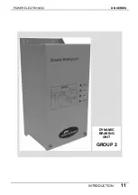
Страница 12: ...POWER ELECTRONICS DB SERIES INTRODUCTION 11 DYNAMIC BRAKING UNIT GROUP 2...
Страница 35: ...DB SERIES POWER ELECTRONICS 34 DYNAMIC BRAKING RESISTOR...
Страница 36: ...POWER ELECTRONICS DB SERIES DYNAMIC BRAKING RESISTOR 35...
Страница 38: ...www power electronics com...

