background image


DB SERIES


POWER ELECTRONICS

4.


INSTALLATION OF DYNAMIC 

BRAKING UNIT 

4.1.


Terminal Configuration 

4.1.1.


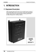
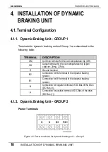
Dynamic Braking Unit – GROUP 1 

Terminals for dynamic braking units of Group 1 are described in the 

following table: 


TERMINAL 

DESCRIPTION 

CM 

Common terminal for the over-temperature trip (OH). 
Output terminal for the over-temperature trip (Open 

collector: 20mA, 27Vdc). 

OH 

G Ground 

terminal. 

Connection for B2 terminal of the dynamic braking 

resistor. 

B2 

Connection for B1 terminal of the dynamic braking 

resistor. 

B1 

Connection for negative terminal of DC Bus of the drive 

(DC Bus (-)). 

Connection for positive terminal of DC Bus of the drive 

(DC Bus (+)). 

4.1.2.


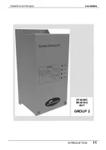
Dynamic Braking Unit – GROUP 2 

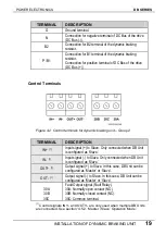
Power Terminals 


Figure 4.1 Power terminals for dynamic braking unit – Group 2 


18 

INSTALLATION OF DYNAMIC BRAKING UNIT 

Содержание SDRIVE DB Series

Страница 1: ...DB Series SDRIVE S D Y N A M I C B R A K I N G dynamic braking unit Getting Started Manual...

Страница 2: ...dynamic braking unit Getting Started Manual Edition October 2007 VFDF01AI Rev A...

Страница 3: ...DB SERIES POWER ELECTRONICS 2...

Страница 4: ...tage may be present Maintenance operation should be done by qualified personnel Edition October 2007 This publication could present technical imprecision or misprints The information here included wil...

Страница 5: ...DB SERIES POWER ELECTRONICS 4...

Страница 6: ...F DYNAMIC BRAKING UNIT 16 3 1 Environmental Conditions 17 4 INSTALLATION OF DYNAMIC BRAKING UNIT 18 4 1 Terminal Configuration 18 4 2 Leds Description 20 4 3 Terminals of Braking Resistor 21 4 4 Conne...

Страница 7: ...DB SERIES POWER ELECTRONICS 6 INDEX...

Страница 8: ...or exposure of charged capacitors Do not remove the cover except for periodic inspections or wiring even if the input power is not applied Otherwise you may access the charged circuits and get an elec...

Страница 9: ...he resistor is still hot Do not apply power to a damaged drive or braking unit or to a drive or braking unit with parts missing even if the installation is complete Otherwise fire or accident could oc...

Страница 10: ...t Wear safety glasses when operating the braking unit close to the drive with power applied and the front cover is removed Handle the braking unit with care according to its weight Do not place heavy...

Страница 11: ...perating with drives which do not include dynamic braking circuit as standard and it is necessary to conduct the regenerated energy it will connect an optional dynamic braking unit with the correspond...

Страница 12: ...POWER ELECTRONICS DB SERIES INTRODUCTION 11 DYNAMIC BRAKING UNIT GROUP 2...

Страница 13: ...ynamic braking unit for drives from 3 7 to 11kW 400V DBSD4030 1 3 SD45024 SD700245xxxx 3 SD45030 SD700325xxxx 1 Dynamic braking units for drives from 15 to 18 5kW 400V DBSD4045 2 4 SD45039 SD700385xxx...

Страница 14: ...ave control signal Output signal Heat sink overheat Protection Heat sink overheat Heat sink overheat overcurrent Ambient 10 C to 40 C 10 C to 40 C Temp Humidity 90 non condensing 90 non condensing Alt...

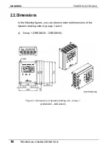
Страница 15: ...ns In the following figures you can observe external dimensions of the dynamic braking units of groups 1 and 2 a Group 1 DBSD4030 DBSD4045 Figure 2 1 Dimensions of dynamic braking unit Group 1 DBSD403...

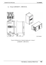
Страница 16: ...POWER ELECTRONICS DB SERIES TECHNICAL CHARACTERISTICS 15 b Group 2 DBSD4075 DBSD4145 Figure 2 2 Dimensions of dynamic braking unit Group 2 DBSD4075 DBSD4145...

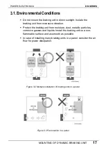
Страница 17: ...UNIT Braking units must be mounted vertically with sufficient horizontal and vertical distance between adjacent equipment A Higher than 100mm B Higher than 50mm Figure 3 1 Dynamic braking unit mountin...

Страница 18: ...sive vibration Protect the braking unit from moisture dust metallic particles corrosive gasses and liquids Install the braking unit on a non flammable surface and as smooth as possible In case of inst...

Страница 19: ...terminal for the over temperature trip Open collector 20mA 27Vdc OH G Ground terminal Connection for B2 terminal of the dynamic braking resistor B2 Connection for B1 terminal of the dynamic braking r...

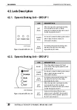
Страница 20: ...raking unit Group 2 TERMINAL DESCRIPTION Input signal to Slave Only connected when DB Unit is configured as Slave IN 1 Input signal to Slave Only connected when DB Unit is configured as Slave IN 1 Out...

Страница 21: ...Unit G1 LED DESCRIPTION Press this switch to release OCT fault overcurrent Pressing this switch the OCT led is turned off RESET It is turned on when the braking unit receives power supply because usua...

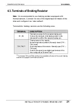
Страница 22: ...NAL DESCRIPTION Terminals to connect to the dynamic braking unit Connect the terminals of the braking resistor to the terminals B1 and B2 of the dynamic braking unit B1 B2 Thermal sensor of the resist...

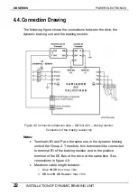
Страница 23: ...nection of the braking resistor trip Notes Terminals B1 and P are the same one in the dynamic braking units of the Group 2 Therefore this terminal will be connected to terminal B1 of the braking resis...

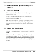
Страница 24: ...raking unit is connected to the drive this one should be configured as Master factory setting To get additional information see section 4 5 2 Master Slave Operation Mode 4 5 2 Master Slave Operation M...

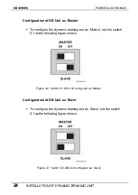
Страница 25: ...t the switch S1 as the following figure shows Figure 4 6 Master Switch S1 DB Unit configured as 7 Switch S1 DB Unit configured as Configuration of DB Unit as Slave To configure the dynamic braking uni...

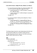
Страница 26: ...aves between them o Connect terminal OUT of the first DB Unit Slave to terminal IN of the second DB Unit configured as Slave o Connect terminal OUT of the first DB Unit Slave to terminal IN of the sec...

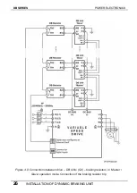
Страница 27: ...SERIES POWER ELECTRONICS Figure 4 8 Connections between drive DB Units G2 braking resistors in Master Slave operation mode Connection of the braking resistor trip 26 INSTALLATION OF DYNAMIC BRAKING UN...

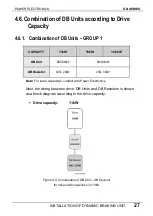
Страница 28: ...1 CAPACITY 11kW 15kW 18 5kW DBSD4030 DBSD4045 DB Unit 30 2 5kW 20 3 5kW DB Resistor Note For lower capacities contact with Power Electronics Next the wiring between drive DB Units and DB Resistors is...

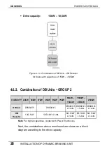
Страница 29: ...kW 55kW 90kW 160kW 75kW 250kW 150kW 200kW DB Unit DBSD4075 DBSD4145 DBSD4145 DBSD4145 DBSD4145 x 2 units x 3 units x 4 units 6 10kW 6 10kW 6 10kW DB 12 5kW 12 5kW x 2 units x 2 units x 3 units x 4 uni...

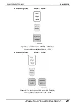
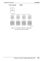
Страница 30: ...NAMIC BRAKING UNIT 29 Drive capacity 22kW 30kW Figure 4 11 Combination of DB Unit DB Resistor for drives with capacities of 22kW 30kW Drive capacity 37kW 75kW Figure 4 12 Combination of DB Unit DB Res...

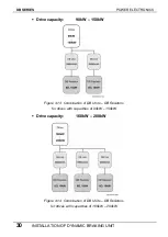
Страница 31: ...kW Figure 4 13 Combination of DB Units DB Resistors for drives with capacities of 90kW 150kW Drive capacity 160kW 200kW Figure 4 14 Combination of DB Units DB Resistors for drives with capacities of 1...

Страница 32: ...POWER ELECTRONICS DB SERIES INSTALLATION OF DYNAMIC BRAKING UNIT 31 Drive capacity 250kW Figure 4 15 Combination of DB Units DB Resistors for drives with capacities of 250kW...

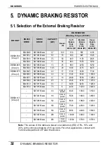
Страница 33: ...2 SD45060 SD700605xxxx 30 12 1500 4500 10500 SD45075 SD700755xxxx 37 10 2000 5550 12950 SD45090 SD700905xxxx 45 8 2500 6750 15750 SD45110 SD701155xxxx 55 7 3000 8250 19250 SD45150 SD701505xxxx 75 6 40...

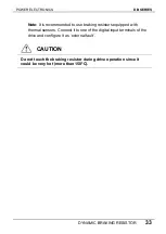
Страница 34: ...commended to use braking resistors equipped with thermal sensors Connect it to one of the digital input terminals of the drive and configure it as external fault CAUTION Do not touch the braking resis...

Страница 35: ...DB SERIES POWER ELECTRONICS 34 DYNAMIC BRAKING RESISTOR...

Страница 36: ...POWER ELECTRONICS DB SERIES DYNAMIC BRAKING RESISTOR 35...

Страница 37: ...ajo 12006 CASTELL N Tel 964 340 378 Fax 964 341 495 Pol Residencial Santa Ana Avda Venecia 17 30319 CARTAGENA MURCIA Tel 968 53 51 94 Fax 968 126 623 NORTE Parq Tecnol gico Vizcaya Edificio 103 Planta...

Страница 38: ...www power electronics com...

Отзывы: