POWER ELECTRONICS
DB SERIES
INSTALLATION OF DYNAMIC BRAKING UNIT
21
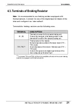
4.3.
Terminals of Braking Resistor
Note:
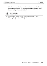
It is recommended to use braking resistors equipped with
thermal sensors. Connect it to one of the digital input terminals of the
drive and configure it as ‘external fault’.
Terminals for braking resistors are the following ones:
TERMINAL
DESCRIPTION
Terminals to connect to the dynamic braking unit.
Connect the terminals of the braking resistor to the
terminals B1 and B2 of the dynamic braking unit.
B1, B2
Thermal sensor of the resistor.
Normal temperature (ambient): Normally closed (TH1 –
TH2 closed).
TH1, TH2
Over-temperature of the resistor: Normally open (TH1 –
TH2 open).
[1]
Connect this signal to one digital input terminal of the
drive configured as 'External Fault'.
[1]
Terminals TH1 and TH2 will be only available whenever the used braking
resistor is equipped with thermal sensor.
Содержание SDRIVE DB Series
Страница 1: ...DB Series SDRIVE S D Y N A M I C B R A K I N G dynamic braking unit Getting Started Manual...
Страница 2: ...dynamic braking unit Getting Started Manual Edition October 2007 VFDF01AI Rev A...
Страница 3: ...DB SERIES POWER ELECTRONICS 2...
Страница 5: ...DB SERIES POWER ELECTRONICS 4...
Страница 7: ...DB SERIES POWER ELECTRONICS 6 INDEX...
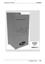
Страница 12: ...POWER ELECTRONICS DB SERIES INTRODUCTION 11 DYNAMIC BRAKING UNIT GROUP 2...
Страница 35: ...DB SERIES POWER ELECTRONICS 34 DYNAMIC BRAKING RESISTOR...
Страница 36: ...POWER ELECTRONICS DB SERIES DYNAMIC BRAKING RESISTOR 35...
Страница 38: ...www power electronics com...

