


Part No. 27/20334
Servicing & Routine Maintenance 27
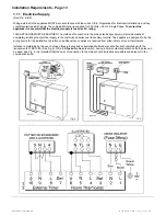
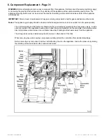
5. Routine Maintenance - Page 27
Routine Maintenance (Carry out the following sequence 5.1 -
5.10)
5.1 Remove the White Front Case
(See Fig. 13 in the Boiler Installation Section).
a.
Remove the two securing screws located at the base
of the white front case assembly.
b.
Ease the base of the case forward approximately
50mm and lift to release the panel from the securing
hooks at the top of the appliance.
c.
Remove the case and place in a safe position away
from the immediate working area.
5.2 Remove Base Panel
a.
Remove the two securing screws retaining the base
panel to the case sides.
b.
Lower the front edge and push backwards to release
cover
5.3 Remove the Air Box Covers
a.
Take out the six securing screws and remove the main
air box cover.
b.
Remove the two screws securing the front edge of the
left hand white case side panel. This will allow the side
panel to be sprung outwards to improve access for the
following operation.
c.
Remove the four screws securing the two remaining air
box side covers and remove.
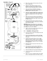
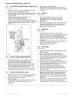
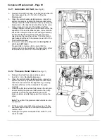
5.4 Remove the Fan Assembly
a.
Disconnect the fan wiring by separating the in-line
connector.
b.
Support the fan and remove the two fixing screws from
the front edge of the fan mounting plate. Lower the fan
and carefully withdraw it from the appliance. Put in a
safe place until required.
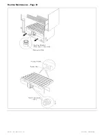
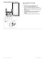
5.5 Remove the Flue Hood
a.
Remove the two flexible tubes connected to the left
and right hand sides of the fluehood.
b.
Slacken the screw on the left-hand rear of the flue
hood (but do not remove) and fully remove the
remaining right hand screw.
c.
Lift and remove the fluehood to expose the top surface
of the heat exchanger.
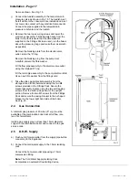
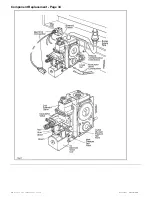
5.6 Remove the Combustion Chamber Front Panel
a.
Remove the two screws securing the combustion
chamber front panel.
b.
Remove the panel by pulling the top edge forwards
and lifting the panel clear of the two lower retaining
flanges. Ensure the insulation remains in position. The
underside of the heat exchanger is now exposed.
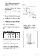
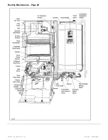
5.7
To Inspect and Clean the Boiler
(See Fig. 23)
a.
Inspect the heat exchanger for any blockage. Deposits
of any material should be brushed away using a soft
brush.
Note:
Do not use brushes with metallic bristles.
b.
Examine internal pipe work connections and automatic
air vent for any water leaks. Rectify if necessary.
c.
Examine the combustion chamber insulating material
and renew if damaged. To remove the combustion
chamber side panels undo the single screw from each
side and pull panel forward. The insulation can now be
removed from the panel. To remove the insulation from
the rear of the combustion chamber remove the burner
and two hexagonal burner location supports and take
out the two screws from the insulation support bracket.
Remove the support and slide the insulation
downwards from behind the heat exchanger.
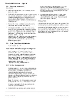
d.
Check the electrodes for damage or deterioration.
Ensure that the spark gaps are correct to dimensions
specified in Fig. 23. Clean or renew as necessary. Do
not bend the electrodes as the insulating material may
crack.
e.
Examine the fan for any mechanical damage (including
seals), check to ensure free running of the fan wheel.
Clean the wheel if necessary with a soft brush.
Note:
It is essential that a good seal is made at the
fan, renew the sealing collar or fluehood sealing ring if
there are any signs of damage or deterioration.
See Section 6.17 of Component Replacement.
f.
Examine flue ducts and flue hood and ensure that
there is no obstruction. Re-assemble all components in
reverse order, (ensure all seals are replaced correctly).
During re-assembly check the air box door and side cover
seals for damage or deterioration and renew if necessary.
Содержание Puma Flowsure+
Страница 5: ...Part No 27 20334 Introduction 5 Introduction Page 5 ...
Страница 28: ...28 Routine Maintenance Part No 27 20334 Routine Maintenance Page 28 ...
Страница 30: ...30 Routine Maintenance Part No 27 20334 Routine Maintenance Page 30 ...
Страница 34: ...34 Component Replacement Part No 27 20334 Component Replacement Page 34 ...
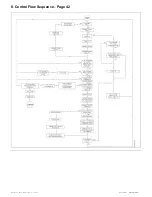
Страница 42: ...42 Control Flow Sequence Part No 27 20334 8 Control Flow Sequence Page 42 ...
Страница 43: ...Part No 27 20334 Functional Flow 43 9 Functional Flow Page 43 ...
Страница 44: ...44 Pictorial Wiring Diagram Part No 27 20334 10 Pictorial Wiring Diagram Page 44 ...
Страница 45: ...Part No 27 20334 Electrical Diagram 45 11 Electrical Diagram Page 45 ...
Страница 47: ...Part No 27 20334 Short List of Spares 47 Short List of Spares Page 47 Back page ...


