


10 Installation Requirements
Part No. 27/20334
Installation Requirements - Page 10
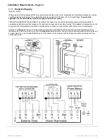
Frost Protection
The tank of hot water will provide frost protection. This is
purely for the protection of the appliance. If any other part of
the central heating system requires frost protection, an
external frost thermostat must be fitted in the usual manner,
refer to Fig. 9 for wiring.
1.6
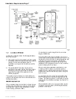
Mains Water Feed: Central Heating
A connection must be incorporated into the central heating
system to facilitate filling. There must be no direct connection
to the mains water supply, even through a non-return valve,
without the approval of the Local Water Authority.
PERMISSIBLE METHODS OF FILLING
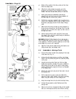
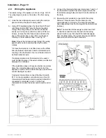
Note:
The Puma combination boiler range is fitted with a
diverter valve design which has a manual operation lever to
aid filling. To ease filling of the pump manifold an air bleed
valve is fitted to the diverter and must be opened during filling
until water flows out. The valve should then be closed.
See Fig.13.
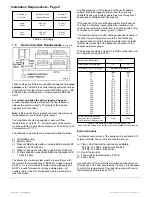
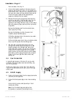
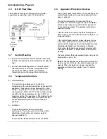
(1) DIRECT METHOD
(Fig. 5)
A detachable flexible hose is connected to a stop valve fitted
to an outlet on the service main. The other end of the hose is
connected to a second stop valve and a double check valve.
The double check valve is fitted to an inlet connection on the
central heating return pipe under the appliance. The hose
should be disconnected after filling. Where the mains pressure
is excessive a pressure reducing
valve shall be used to make filling easier. The following fittings
shall form a permanent part of the system and shall be fitted in
the order stated.
a) A stop valve complying with the requirements of BS
1010 Part 2, (the temporary hose from the draw off tap
shall be connected to this fitting).
b) Double check valve of an accepted type.
(2) BOOSTER PUMP METHOD
The system may be filled through a self contained unit
comprising a cistern, pressure booster pump and if
necessary, an automatic pressure-reducing valve or flow
restrictor.
The pressure booster pump must be capable of pressurising
the system to a minimum of 1.0 bar (14 p.s.i.) measured at the
appliance.
The cistern should be supplied through a temporary
connection from a service pipe or cold water distributing pipe.
The unit may remain permanently connected to the heating
system to provide limited water make-up.
Provisions for make up water
Provision should be made for replacing water loss from the
system by re-pressurisation of the system. See section on
Permissible Methods of Filling.
Reference should be made to British Gas Publications
"Material and Installation Specifications for Domestic Central
Heating and Hot Water".
1.7
Installation to an Existing Central
Heating System
The boilers are designed to operate on a sealed system only,
therefore if the existing system is of the open type it will have
to be modified to comply with BS 6798.
Before installing a new combination boiler to an existing
system flush out the old system with a recommended
descaling/flushing agent at least twice.
Also check pipework and renew any corroded pipework or
fittings. Valve glands must be re-packed or replaced wherever
necessary and any defective controls replaced.
1.8
Hard Water Areas
If the area of installation is recognised as a hard water area,
(above 200 p.p.m.) it is essential that a suitable water
treatment device of an electronic, magnetic or galvanic type be
installed in the mains water supply.
To assess water hardness, immerse the test strip supplied, for
about one second in a water sample (NOT IN RUNNING
WATER) so as to moisten all the zones.
Inspect the strip after 1-2 minutes, check the zones, if two or
more zones have changed colour the hardness of the water is
above 200 p.p.m. and a water treatment device will be
required.
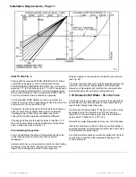
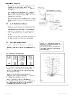
1.9
Pump Performance Curve
The circulating pump fitted within the appliance should be
capable of satisfying most system requirements. Fig. 6
indicates the amount of pump head available for the system.
The boiler resistance is already taken into account in this
curve.
Содержание Puma Flowsure+
Страница 5: ...Part No 27 20334 Introduction 5 Introduction Page 5 ...
Страница 28: ...28 Routine Maintenance Part No 27 20334 Routine Maintenance Page 28 ...
Страница 30: ...30 Routine Maintenance Part No 27 20334 Routine Maintenance Page 30 ...
Страница 34: ...34 Component Replacement Part No 27 20334 Component Replacement Page 34 ...
Страница 42: ...42 Control Flow Sequence Part No 27 20334 8 Control Flow Sequence Page 42 ...
Страница 43: ...Part No 27 20334 Functional Flow 43 9 Functional Flow Page 43 ...
Страница 44: ...44 Pictorial Wiring Diagram Part No 27 20334 10 Pictorial Wiring Diagram Page 44 ...
Страница 45: ...Part No 27 20334 Electrical Diagram 45 11 Electrical Diagram Page 45 ...
Страница 47: ...Part No 27 20334 Short List of Spares 47 Short List of Spares Page 47 Back page ...


