


Part No. 27/20334
Installation 15
2. Installation - Page 15
It is
MOST IMPORTANT
that the appliance is installed in a
VERTICAL POSITION
, with the flue system passing
through the wall or ceiling in a
Horizontal
or
Vertical
plane. A minor deviation from the horizontal is acceptable,
provided that this results in a downward slope of the flue
system away from the combination boiler.
2.1
Unpacking
The appliance will arrive on site in three separate
cardboard cartons. Unpack the cartons and check the
contents against the contents lists.
(1) The Boiler
(2) The Flue System.
There is a range of horizontal and vertical flue
systems and optional packs (i.e. extensions / in-
line bends etc.) to suit your requirements which
are supplied separately from the boiler and include
Installation Instructions - See Page 8.
(3) The Tank
2.2
Installation - Boiler
Caution
Some residual water may still be in the
heat exchanger and pipework.
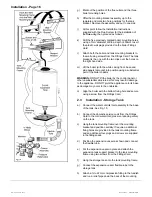
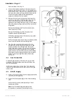
a) Remove the white front case as follows; undo the two
securing screws at the base of the panel, pull the base
of the panel forward approx. 50mm and lift off the
supporting top hooks. (See Fig. 13)
b) Remove the base cover by removing the two fixing
screws and push the cover towards the rear to release
c)
Each side panel can now be individually removed by
removing the two front fixing screws, loosening the
lower rear fixing screw and sliding the panel upwards
to unhook from the upper rear fixing. Place each panel
and screws safely to one side. The lower rear fixing
screw from the right hand side will have to be removed
completely before the side panel can be removed.
d) Position the appliance onto its side and remove the
four screws retaining the lowest rear cross brace. This
brace is for transit purposes only and should be
discarded. Remove all plastic plugs from the pipes.
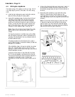
e)
Connections:
All connections for the boiler & tank are
supplied on the Fittings Card or in the box containing
the water inlet controls assembly. Remove the fittings
for the boiler and assemble to the appliance. See Fig.
12.
Note:
When fitted, the Red levered central heating tail
(C.H.flow) should be to the left of the Blue.
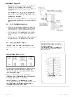
f)
Tape the wall fixing template to the wall in the selected
appliance position. Allow an extra 475mm from the
right hand edge of the template for the tank (including
clearances).
Содержание Puma Flowsure+
Страница 5: ...Part No 27 20334 Introduction 5 Introduction Page 5 ...
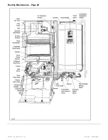
Страница 28: ...28 Routine Maintenance Part No 27 20334 Routine Maintenance Page 28 ...
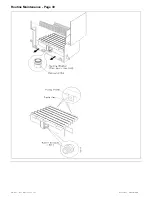
Страница 30: ...30 Routine Maintenance Part No 27 20334 Routine Maintenance Page 30 ...
Страница 34: ...34 Component Replacement Part No 27 20334 Component Replacement Page 34 ...
Страница 42: ...42 Control Flow Sequence Part No 27 20334 8 Control Flow Sequence Page 42 ...
Страница 43: ...Part No 27 20334 Functional Flow 43 9 Functional Flow Page 43 ...
Страница 44: ...44 Pictorial Wiring Diagram Part No 27 20334 10 Pictorial Wiring Diagram Page 44 ...
Страница 45: ...Part No 27 20334 Electrical Diagram 45 11 Electrical Diagram Page 45 ...
Страница 47: ...Part No 27 20334 Short List of Spares 47 Short List of Spares Page 47 Back page ...