5401587 - REV B • 6/21
PAGE 5 OF 10
Potter Electric Signal Company, LLC • St. Louis, MO • Phone: 800-325-3936 • www.pottersignal.com
SignaLink
™
Bridge
Wireless Supervisory System
Testing
1. Activate the sprinkler switch. The Alarm/Supervisory relay on the Receiver shall change states within 10 seconds.
2. Restore the sprinkler switch back to the normal state. The Alarm/Supervisory relay on the Receiver shall restore back to normal within 10 seconds.
3. Disconnect a wire from the Transmitter to the sprinkler device. The trouble relay on the Receiver shall change states within 10 seconds.
4. Reconnect the wire to the sprinkler device. The Trouble relay on the receiver shall restore to normal within 10 seconds
5. Remove the cover on the Transmitter allowing the cover tamper switch to activate. The trouble relay on the Receiver shall change state within 10
seconds.
6.
Depress the cover tamper on the Transmitter. The trouble relay on the Receiver shall restore to normal within 10 seconds.
7. Remove the battery from the Transmitter. The trouble relay on the Receiver shall activate within 84 seconds.
8. Reinstall the battery in the Transmitter. The trouble relay on the Receiver shall restore to normal within 10 seconds.
9. Replace the cover on the Transmitter and make sure the Receiver is in a normal condition.
10.
Repeat steps 5 and 6 for any repeaters.
Note:
The times noted above are the maximum times allowed. Actual times will be significantly less with the possible exception of the missing battery test.
Battery status is checked every 84 seconds so it depends where in that 84 second timing cycle the battery was removed.
WR - Repeater
Per NFPA 72, if the repeater is powered by an external power supply, the repeater is allowed to support multiple transmitters and receivers. Although
the repeater may support more than one receiver, it can only be paired to one receiver. This selected receiver will display the status of the repeater.
If a repeater is powered by a battery, that repeater shall only serve one transmitter/receiver set. This is so that in the event that if the repeater loses its
sole source of power, it does not affect more than one transmitter/receiver set.
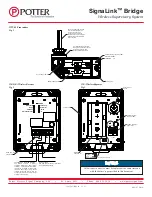
The Wireless Repeater is designed to be mounted to a wall or a post using the optional post mounting kit, see fig. 6. When installing the Repeater
outdoors, it may be necessary to install the device so that it is above vehicular traffic.
When mounting to a wall make sure the surface is flat enough to activate the pry-off tamper on the back of the unit. When mounting to a post, follow
the instructions that come with the post mounting kit to ensure that the pry-off tamper on the back of the Repeater will operate correctly.
There is a weatherproof rubber plug in the conduit entrance on the bottom of the Repeater enclosure. When powering the Repeater with batteries, leave
the weatherproof plug in place. When using an external power source, remove the plug to connect the conduit. The Repeater can be powered by an on-
board battery or an external power supply. It is shipped from the factory in the External Power mode. To switch to battery power, remove the 4 screws
holding the cover in place and move the jumper from Com and Ext Power to Batt & Com. See fig. 3.
For class A operation, the repeater must be powered by a UL 864 or 1481 listed supply with battery backup. Every repeater must have a backup repeater
to provide dual communication paths and each repeater must have it’s own UL864 or 1481 battery backed up power supply so the loss of one power
source only affects one repeater. If the system would normally require one repeater, two must be used. If the application would normally require two,
four must be used, etc.
Please note, only 3 repeaters can be paired to a receiver. If additional repeaters are required for class A operation, the additional repeaters would be
paired to subsequent receivers.
After the devices are paired and installed, the signal strength between all devices should be checked using the Wireless Setup Tool. The signal
strength between all devices shall be above a minimum of 53%. Anything below 53% may result in communication errors. See document 5406108
for information about the setup tool.
Battery Information
The batteries will last 1 year under normal use. When the battery level reaches a point where there is a minimum of seven days of power left, the
Transmitter and/or Repeater if powered by batteries will transmit a low battery signal to the Receiver. At this point the batteries should be replaced
as soon as possible with the correct batteries. The batteries may last longer than 7 days from the initial low battery signal. Additional life depends on
temperature, signal strength and number of transmissions. It is possible to determine remaining battery capacity using the Potter Setup Tool.
Testing of the wireless devices shall be conducted upon completion of the installation and periodically thereafter in accordance with the testing
requirements of the devices they are monitoring, applicable NFPA codes and ordinances and/or the authority having jurisdiction. (Manufacturer
recommends quarterly or more frequently)


