5401587 - REV B • 6/21
PAGE 3 OF 10
Potter Electric Signal Company, LLC • St. Louis, MO • Phone: 800-325-3936 • www.pottersignal.com
SignaLink
™
Bridge
Wireless Supervisory System
Device Pairing
The Potter wireless devices do not require any programming to operate. The only requirement is to pair together the devices that will communicate with
each other on the network to form a wireless system. This can be accomplished in one of two ways.
1. Use the Wireless Setup Tool on a laptop to enter the unique MAC ID of the transmitter and receiver that will be communicating with each other
on the wireless system. This process is described in the literature with the Setup Tool.
2. Cycle the power on the transmitter and receiver to put them in Learn Mode and then use the cover tamper switches on each to force them to send
their MAC IDs to each other. This process is described in the following section.
Important:
Please read all the pairing steps BEFORE starting the process so you are familiar with it. Have both devices to be paired on a workbench
and have the necessary power supply/batteries ready to be connected/inserted.
The transmitter and repeater (if used) must be paired to the receiver to allow them to communicate with each other. The transmitter and repeater are
individually paired to the receiver. First pair the transmitter to the receiver. If repeaters are used, they will be individually paired one at a time to the receiver
after the transmitter pairing is complete.
Note:
When power is first applied to the devices, they go through a power-up cycle for about 3 seconds. All the LEDs on the devices will flash during this
time. After the 3 second power-up process, they are in Learn Mode for about 40 seconds. The pairing must occur during the Learn Mode.
IMPORTANT NOTICE REGARDING BATTERY LIFE
Battery operated devices spend most of their time in battery conservation mode. They only communicate to indicate an event or for the required
periodic supervision signal to the receiver. The receiver then puts the device back into conservation mode. Do not leave batteries in a device that is not
installed as part of an active system with an operating receiver. If a battery powered device does not receive confirmation from the receiver, the device
will continuously try to contact the receiver resulting in a low battery alert within a few days. If devices are not immediately going to be installed after
pairing, remove the batteries after pairing. The pairing will remain after battery removal.
LED Conditions in Learn Mode:
•
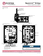
On the receiver, only the WTX-M & WR LEDs will flash simultaneously. See fig. 2, page 7 for location of LEDs.
•
On the transmitter, only the BATT RST LED will flash. See fig. 1, page 7 for location of LEDs.
Pairing Process:
1. Apply 24 VDC to the receiver.
2. Install the batteries in the transmitter/repeater (or apply 24 VDC power supply to the repeater if used).
3.
Wait about 3 seconds until only 1 LED on the transmitter is flashing and only 2 LEDs on the receiver are flashing.
4. SLOWLY press the transmitter/repeater cover tamper switch holding it down long enough each time to make sure the 2nd LED on the transmitter /
repeater turns on each time the switch is pressed.
5.
After the 5th activation of the switch/lighting of the 2nd LED, both LEDs on the transmitter/repeater will flash rapidly for a few seconds.
6.
The devices should now be paired. Verify a successful pairing by releasing the tamper. The WRX-R should display a tamper error for that transmitter/
repeater.
The Learn Mode LEDs will continue to flash until the Learn Mode times out. There is no need to do anything during this time. When the Learn Mode LEDs
stop flashing, the devices are ready to be put in service. If a repeater needs to be paired, remove power from the receiver and start over at step 1 above. The
devices will remain paired together even after power is removed. There is no need to re-pair them after removing power and re-applying power for field
installation.
If multiple repeaters are paired, the technician should record on each Repeater whether it was the first, second or third repeater paired to aid in
troubleshooting later. Repeaters must be installed in the order in which they were paired. Repeater # 1 should be closest to the receiver and repeater #3
is closest to the transmitter.


