


PST-6000 series Technical Manual 7 - 2
TM
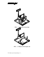
an intermediate cable of the internally connected KB wedge device if assembled in
accordance with the instructions given in the User’s Manual; a four wire cable
connecting to the KB CPU board from somewhere near the power supply unit; an
intermediate socket connecting to the LED on the programmable keyboard unit. Then
the keyboard unit can be taken away and put aside. However, to prevent a messy
situation for reinstallation later on, the two (or one if an internally connected KB
wedge device exists) cable stopper from both sides of the bottom chassis should be
taken out and kept well (see DWG.-4).
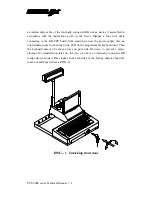
DWG. - 1 Unlocking front door
Содержание PST-6000 SERIES
Страница 1: ...TM Rev A L 1 L 0 L P L 2 L 3 L 4 L 1 L 0 L P L 2 L 3 L 4 PST 6000 SERIES TECHNICAL MANUAL ...
Страница 8: ...vi TM ...
Страница 20: ...PST 6000 series Technical Manual 2 10 TM ...
Страница 22: ...PST 6000 series Technical Manual 3 2 TM ...
Страница 58: ...PST 6000 series Technical Manual 5 28 TM ...
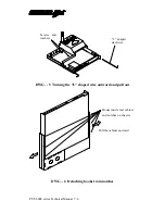
Страница 73: ...PST 6000 series Technical Manual 7 3 TM DWG 2 Unscrew the bottom ...
Страница 74: ...PST 6000 series Technical Manual 7 4 TM DWG 3 Lifting the keyboard unit DWG 4 Taking the cable stoppers out ...
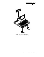
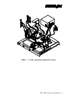
Страница 77: ...PST 6000 series Technical Manual 7 7 TM DWG 7 Cable connections inside PST system ...
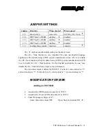
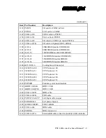
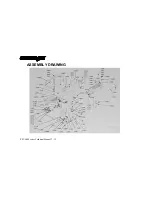
Страница 82: ...PST 6000 series Technical Manual 7 12 TM ASSEMBLY DRAWING ...


