background image

PST-6000 series Technical Manual 2 - 2

TM

OPERATOR DISPLAY

CRT display (VGA interface)

 – for PST 6000

Display Type

9” monochrome CRT

10” color CRT

Size

228 mm (9”) diag.

175 (6.9”) * 125 (4.9”) mm

Resolution

800 * 600 max.

1024 * 768 max.

Position movable range

Back & forth: 48mm (1.890

) max.

Left to right: 30mm (1.181

) max.

Swivel range

90

°

left, 90

°

right

Tilt angle

20

°

max.

Power source

(UPS supported)

Included in VGA

display connector

AC input from output outlet

of system power

Video memory

Shared from system memory,

programmable through CMOS setup

Note:

 10” color monitor uses AC power and is not UPS supported.

12.1” COLOR LCD

 –for PST 6030

Display Type

Color DSTN –LCD

View area

247 (9.7”) (W) * 186 (7.3”) (H) mm

Resolution

800 * 600

Memory size

1 MB

Swivel range

45

°

left, 30

°

right

Tilt angle

90

°

max

Back light

Side-edge CFL * 2

Luminance

150 cd/m

2

Knob control

Brightness and Contrast

Signal interface

TTL

Signal connector

50 pin SCSI connector

Power source

included in display connector

Содержание PST-6000 SERIES

Страница 1: ...TM Rev A L 1 L 0 L P L 2 L 3 L 4 L 1 L 0 L P L 2 L 3 L 4 PST 6000 SERIES TECHNICAL MANUAL ...

Страница 2: ...00 series which is a member of the POSIFLEX integrated point of sale terminal product family The PST6000 is a compact point of sale system that gives the most user friendly upgrade transition from ECR and combines the performance and affordability of personal computers with the elegance and reliability of business machine The PST6000 also provides the built in networking capability for easy commun...

Страница 3: ...ST 6000 2 2 LCD 12 1 for PST 6030 2 2 LED COLOR 2 3 SYSTEM POWER ON OFF CONTROL 2 3 UPS SUPPORT BATTERY OPTION 2 3 24VDC POWER SUPPLY TO POS PRINTER 2 3 INPUT OUTPUT PORTS 2 4 HDD 2 4 PRELOAD DOS 2 4 EXTERIOR 2 4 PROGRAMMABLE KEYBOARD 2 5 ENVIRONMENTAL 2 5 ACCESSORIES 2 6 OPTIONS 2 7 CUSTOMER DISPLAY 2 7 KEY TOP OPTION 2 7 UPS BATTERY 2 7 INTERNAL MODEM CARD 2 7 IRDA TRANSCEIVER 2 7 ...

Страница 4: ...SPECIFICATION 3 1 SYSTEM DEFINITIONS 4 1 BLOCK DIAGRAM 4 1 EXTERNAL KEYBOARD CONNECTOR 4 2 LAN PORT 4 2 PS 2 MOUSE 4 2 CRT DISPLAY PORT CONNECTOR 4 3 LCD DISPLAY PORT CONNECTOR 4 3 SERIAL PORT COM1 4 3 SERIAL PORT COM2 4 4 SERIAL PORT COM3 4 5 SERIAL PORT COM4 4 5 PARALLEL PORT LPT1 4 6 CUSTOMER DISPLAY CONNECTOR 4 7 CASH DRAWING CONTROLLER 4 7 USB1 4 7 USB2 4 7 24 VDC CONNECTOR 4 8 UPS BATTERY CO...

Страница 5: ...ard 5 9 Epson mode 2 lines x 20 characters 5 10 Noritake mode 2 lines x 20 characters 5 12 Epson mode 4 lines x 26 characters 5 15 PROGRAMMABLE KEYBOARD 5 17 HOT KEY PROGRAMMING 5 17 Preparation 5 17 Enter Hot key programming mode 5 17 Input the content to be programmed 5 18 Exit Hot key programming mode 5 18 COMMON PROGRAMMING KBM EXE 5 19 Command listing in view mode 5 19 Command listing in ASCI...

Страница 6: ...clock select 6 5 CLOCK ratio select 6 6 Example CPU jumper settings 6 6 DRAM bank select 6 7 Acceptable DRAM configurations 6 7 DIMM socket voltage select 6 7 Cache size select 6 8 Internal VGA select 6 8 Internal VGA ID select 6 8 CMOS memory select 6 8 Customer display handshaking select 6 8 COM1 DC supply select 6 9 COM2 DC supply select 6 9 COM3 DC supply select 6 9 COM4 DC supply select 6 9 C...

Страница 7: ...PARE PARTS MODULE LIST 7 8 ASSEMBLY DRAWING 7 12 APPENDIX Font Tables For Posiflex Customer Displays Appendix 1 CONTENTS Appendix 2 FONT FOR PD 2101 PAGE 0 Appendix 3 FONT FOR PD 2101 PAGE 1 Appendix 4 FONT FOR PD 2101 EPSON PAGE 0 Appendix 5 FONT FOR PD 2101 EPSON PAGE 1 Appendix 6 FONT FOR PD 7001 PAGE 0 Appendix 7 FONT FOR PD 7001 PAGE 1 Appendix 8 FONT FOR INTERNATIONAL CHARACTER SET Appendix ...

Страница 8: ...vi TM ...

Страница 9: ... hardware software application l Highest performance in most compact size point of sale system l Most cost effective with top quality reliability and serviceability of point of sale system at reasonable price l Powerful programming ability hot key programming programming under Windows multiple page multiple level whole range key content time delay position sense answer back code covering most ECR ...

Страница 10: ...CRT DISPLAY PST6000 12 1 color DSTN LCD DISPLAY PST6030 Note The order for PST6000 will not automatically cover the monitor The user should order for the 9 monochrome CRT or the 10 color CRT separately The PST6000 itself is delivered without monitor display but with the monitor tilt swivel base However the PST6030 is delivered with the 12 LCD panel together with its special base ...

Страница 11: ...isplay One PCI slot will be occupied if the LCD display is used However there will be always two I O windows occupied by the system l DCI Technology for best compatibility of input devices l Non volatile Static Random Access Memory 32KB expandable to 64KB max option POWER SOURCE Item Specification High range of voltage input 180 264 Vac Low range of voltage input 90 130 Vac Input frequency 47 63 H...

Страница 12: ...ncluded in VGA display connector AC input from output outlet of system power Video memory Shared from system memory programmable through CMOS setup Note 10 color monitor uses AC power and is not UPS supported 12 1 COLOR LCD for PST 6030 Display Type Color DSTN LCD View area 247 9 7 W 186 7 3 H mm Resolution 800 600 Memory size 1 MB Swivel range 45 left 30 right Tilt angle 90 max Back light Side ed...

Страница 13: ...n be programmed as the software shutdown control according to POSIFLEX standard UPS SUPPORT battery option l Supports system operation for 3 8 min depending on loading condition of 24V printer and whether the UPS is fully charged l STANDBY LED turned on when UPS stand by at power on or AC power present during system off l STANDBY LED flashes and system beeps when UPS starts working and discharging...

Страница 14: ...s option l 1 X VGA display port for PST 6000 1 X LCD display port for PST6030 Both include UPS supported DC power l 1 X 24 VDC 2 Amp Power supported by UPS function l UPS connector for 2 3AH 12V Lead Acid battery or above l 2 USB ports l 1 fast IRDA port IRDA transceiver option l 1 PS 2 mouse port connector cable option HDD l 1GB OR ABOVE PRELOAD DOS l MS DOS 6 22 preload WINDOWS 95 as option EXTE...

Страница 15: ...ws 3 1 or Windows95 without TSR or DLL program l Multi page programming l Multi level programming l Programmable output speed control l Time delay programming l Hot key programming teach learn l Answer back signal when position key changed or when enquired l Standard layout includes one quad key two double keys 12 numeric keys 00 0 9 and 92 pieces of single keys The single keys double keys and qua...

Страница 16: ...L KEY FOR FRONT DOOR 2 PCS l TRANSPARENT KEY CAPS FOR SINGLE KEY 92 PCS FOR DOUBLE KEY 2 PCS FOR QUAD KEY 1 PC l KEY CLIP FOR REMOVAL OF KEY CAPS 1 SET l POWER CABLE FOR 24 V DC CCBLA 146 1 PC l CABLE FOR CASH DRAWER CONTROL CCBLA 180 FOR CR 3100 CR3200 l POWER CORD l CABLE TIE 5 PCS l VELCRO PATCHES FOR PRINTER INSTALLATION 4 PCS l DISKETTE FOR DRIVER UTILITY l COM 1 TERMINATOR 1 PC MOUNTED ON MA...

Страница 17: ...n dot matrix format 5 X 7 8 x 16 16 x 16 or 6 x 8 Character color Green 505 nm Dark blue Horizontal slide mm 95 95 Horizontal rotation 360 360 Inclined viewing angle 14 5 and 30 14 5 and 30 Display area mm x mm 216 x 32 196 x 42 4 KEY TOP OPTION l QUAD KEY l DOUBLE KEY l SINGLE KEY l BLANK KEY UPS BATTERY l 2 3 AH 12V LEAD ACID BATTERY INTERNAL MODEM CARD l AFM100 CUSTOMIZED SIZE TO FIT INTO THE S...

Страница 18: ...ARD 2 SIMM SOCKETS FOR 4MB ea 8MB ea AND 16MB ea EDO DRAM l ON BOARD 2 DIMM SOCKETS FOR 16MB ea EDO DRAM 32MB ea AND 64MB ea SDRAM PRINTER PP 3000 l DOT MATRIX 9 PIN l HIGH SPEED BI DIRECTIONAL l FRICTION TYPE l 40 COLUMNS FOR 15 4 CPI l ACCEPTS PAPER WIDTH 2 25 3 3 25 INCHES WITH ADJUSTABLE PAPER GUIDE l PRINTS ON ORDINARY OR UP TO 3 FOLD CARBONLESS COPY PAPER ...

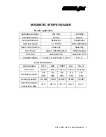
Страница 19: ...unction Read only Read only Life of head Approx 300 000 passes 300 000 passes Error rate Less than 0 5 Less than 0 1 Available models Tracks 1 2 or tracks 1 2 3 JIS II Card data format Card standard IATA ABA THRIFT JIS I JIS II Track used Track 1 Track 2 Track 3 Track 2 Rear side Recording method F2 F FM F2 F FM F2 F FM F2 F FM F2 F FM Recording density 210 BPI 75 BPI 210 BPI 35 BPI 210 BPI Record...

Страница 20: ...PST 6000 series Technical Manual 2 10 TM ...

Страница 21: ...S l LCD PANEL LIFE EXPECTANCY 50 000 HRS l LCD BACK LIGHT LIFE EXPECTANCY 20 000 HRS l FDD MTBF 30 000 HRS l HDD MTBF 50 000 HRS l NVSRAM DATA HOLD TIME 10 YRS l VFD LIFE EXPECTANCY 30 000 HRS l MSR LIFE EXPECTANCY 300 000 PASSES l KEY SWITCH LIFE EXPECTANCY 10 000 000 STROKES l 6 POSITION KEY LIFE EXPECTANCY 25 000 TIMES ...

Страница 22: ...PST 6000 series Technical Manual 3 2 TM ...

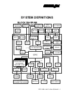
Страница 23: ...4 VDC SERIAL PRINTER COM 1 CUSTOMER DISPLAY 5 VDC CR CR3X00 CR3X00 PS 2 MOUSE PS 2 MOUSE DRAM USB 2 CUSTOMER DISPLAY USB 1 USB DEVICE USB DEVICE CACHE PROGRAMMABLE KEYBOARD MEMORY 8KB MSR COM 4 FDD VGA COM 2 DEVICE DEVICE CRT COM 3 PST033 for PST6030 IRDA PST055A KEYBOARD WEDGE BARCODE SCANNER DEVICE EXT KB PORT PC KB IRDA DEVICE LCD 5 VDC 12VDC PASS THROUGH UPS MGMT HDD ...

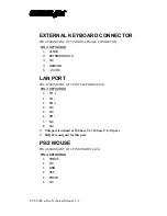
Страница 24: ...CK 2 KEYBOARD DATA 3 NC 4 GROUND 5 5 VDC LAN PORT PIN ASSIGNMENT OF 8 PIN TELEPHONE JACK PIN DEFINITION 1 TD 2 TD 3 RD 4 NC 5 NC 6 RD 7 NC 8 NC This port is defined as 100 base T or 10 base T LAN port IRQ 10 is assigned for this port PS 2 MOUSE PIN ASSIGNMENT OF 6 PIN MINI DIN JACK PIN DEFINITION 1 PMDAT 2 NC 3 GND 4 VCC 5 PMCLK 6 NC ...

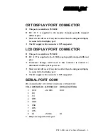
Страница 25: ... This port is available in PST6030 l DC 12 V is supplied to the LCD through specially designed different pins Permanent damage could occur if this connector is connected disconnected while system power on Short circuit will occur if any device other than the designated display is connected to the display port The DC supply in this connector is UPS supported SERIAL PORT COM1 PIN ASSIGNMENT OF 9 PIN...

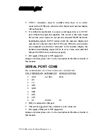
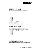
Страница 26: ... system issues any command to cash drawer controller or the customer display the hardware handshaking signal will be in error status and could halt this port if COM1 is not connected properly DC supply of this port is UPS supported Jumper selection please refer to the description in Hardware details of this manual SERIAL PORT COM2 PIN ASSIGNMENT OF 9 PIN D SUB MALE CONNECTOR PIN DEFINITION ALTERNA...

Страница 27: ...signed IRQ9 DC supply of this port is UPS supported Jumper selection please refer to the description in Hardware details SERIAL PORT COM4 PIN ASSIGNMENT OF 9 PIN D SUB MALE CONNECTOR PIN DEFINITION ALTERNATIVE DEFAULT SETTING 1 DCD 12 VDC DCD 2 RX 3 TX 4 DTR 5 GND 6 DSR 7 RTS 8 CTS 9 RI 5 VDC RI IRQ assigned IRQ5 DC supply of this port is UPS supported Jumper selection please refer to the descript...

Страница 28: ...6 D4 D4 D4 7 D5 D5 D5 8 D6 D6 D6 9 D7 D7 D7 10 ACK INTR ACK 11 BUSY WAIT BUSY PeriphAck 12 PE NU Perror AckReverse 13 SLCT NU SLCT 14 AUTO FEED Datastb AutoFeed HostAck 15 ERROR NU Fault PeriphRequest 16 INIT NU Init ReverseRequest 17 SLCT IN NU SLCT IN 18 GND GND GND 19 GND GND GND 20 GND GND GND 21 GND GND GND 22 GND GND GND 23 GND GND GND 24 GND GND GND 25 GND GND GND IRQ 7 is assigned for this...

Страница 29: ...will not function properly l DC supply to this device is UPS supported CASH DRAWER CONTROLLER l The cash drawer solenoid input is a 200 msec grounding signal l The power to cash drawer solenoid is DC 12 V nominal l The command to open cash drawers is decoded through COM 1 l The drawer open indication can be detected by software through status check on RI signal of COM 1 USB1 PIN ASSIGNMENT OF 4 PI...

Страница 30: ...PS supported PIN ASSIGNMENT OF 3 5φ DC JACK PIN DEFINITION CENTER 24 VDC OUTER GND PIN ASSIGNMENT OF 3 PIN PLUG TO PRINTER PIN DEFINITION 1 24 V 2 GND 3 N C CASE CHASSIS GND UPS BATTERY CONNECTOR PIN ASSIGNMENT OF 4 PIN SOCKET PIN DEFINITION 1 12 V 2 12 V 3 GND 4 GND 24 VDC 1 3 CASE 2 PIN 1 ...

Страница 31: ...ftware command to open the cash drawer or the first cash drawer with the optional split cable CCBLA 238 is a hexadecimal code of 07 sent to COM1 port under the protocol of 9600bps none parity 8 data bits 1 stop bit The software command to open the second cash drawer with the optional split cable CCBLA 238 is a hexadecimal code of 17 sent to COM1 port under the same protocol as above The drawer ope...

Страница 32: ...mulate a disk drive To have the NVSRAM work as a simulated disk drive the user should first simply copy the NDISK SYS file from the diskette attached to a convenient directory of his her Hard Disk Drive say copy the file NDISK SYS to the subdirectory C PATH where PATH means the subdirectory routing required add following sentence into the CONFIG SYS file DEVICE C PATH NDISK SYS or DEVICEHIGH C PAT...

Страница 33: ...isplayed please refer to the appendix of this manual The 5 x 7 fonts used in PD 2101 page 0 PD 2101 page 1 PD 2101 EPSON emulation page 0 and PD 2101 EPSON emulation page 1 describe PD2101 The 8 x 16 fonts used in PD 7001 page 0 PD 7001 page 1 and international character sets describe PD7001 However the simplified Chinese characters in PD7011 and the traditional Chinese characters in PD7021 are no...

Страница 34: ...D2101 ADM PD2101ADM Epson SW 1 on off on on off SW 2 on on off off off On the VFD there are totally at most 40 characters in 2 rows to be displayed at the same time while each character displayed in the format of 5 by 7 rectangular dot matrix To the lower right corner of each dot matrix there are a round shaped dot and a tail to form period and comma marks For the characters in 2nd row of the VFD ...

Страница 35: ...otifies the tail to form a comma and P83 denotes the under mark These notations will be used in user defined fonts Futaba emulation mode Command Name Hex Codes Command Name Hex Codes Reset 1F Cursor on 13 Brightness control 04 bb Cursor off 14 Change font page 1E 0p Horizontal tab 09 Moving sign 05 0D Line feed 0A Change leading code 06 x1 x2 Horizontal tab 11 09 Set pass through flag 01 Vertical ...

Страница 36: ...b Cursor up down 11 0A Digit select 1B 48 pp Line feed 12 0A Cursor blinking Rate 1B 54 nn Form feed 0C User defined graphics fonts 1B 43 ad x1 x5 Carriage return 0D Aedex emulation mode not for PD2101ADM Attention code Function code Data Carriage return Function Code Command Name Function Area Data Length 1 Display top Top row Max 20 characters 2 Display bottom Bottom row Max 20 characters 4 On g...

Страница 37: ...cursor to bottom position US B 1F 42 Set cancel display screen blinking US E 1F 45 Move cursor to leftmost position CR 0D Brightness adjustment US X 1F 58 Move cursor to rightmost position US CR 1F 0D Set display counter time US T 1F 54 Move cursor to specified position US 1F 24 Display counter time US U 1F 55 Set cancel user defined characters ESC 1B 25 Initialize display ESC 1B 40 Define user de...

Страница 38: ...and Name Function Area 0C h Clear Display Line 1 Line 2 0D h Carriage Return End of Command 0E h Write Line 1 Line 1 0F h Write Line 2 Line 2 10 h Write Decimal Point Line 1 11 h Blink Line Line 1 or Line 2 12 h Clear Blink Line 1 or Line 2 1E h Write Field 1 Left 8 characters of Line 2 1F h Write Field 2 Right 8 characters of Line 2 ...

Страница 39: ... SETTINGS ON CONTROL BOARD SW1 SW2 for power on default emulation mode SW2 SW1 OFF ON OFF EPSON 2 X 20 NORITAKE 2 X 20 ON EPSON 4 X 26 N A see NOTE OFF ON SW3 NO LOGO AT POWER ON SHOW LOGO AT POWER ON J4 N A Default NOTE The switch position to have both SW1 and SW2 ON is absolutely forbidden in PD7001 This combination is reserved for PD7011 PD7021 that uses second CPU for complicated font handling...

Страница 40: ...SC Define user defined character Max 3 characters multiple definition in 1 command every time new define command will overlay old definition from the first character ref 4 4 for x1 to x16 1B h 26 h s n m a x1 x2 x16 m n 1 where s 2 a 8 n starting address m ending address ESC Select peripheral device n 1 pass through selected n 2 display selected n 3 pass through display both selected Reset display...

Страница 41: ...ight most position 1F h 0D h US Move cursor to the specified position 1F h 24 h n m n th column m th line US Set start ending position of macro definition max 60 byte commands Macro definition and user defined characters can not exist at the same time 1F h 3A h US Execute self test show version show overwrite vertical horizontal scroll modes show all characters of current code table 1F h 40 h US B...

Страница 42: ...d row If the current position is the LSD of the 2nd row the cursor will move to MSD the 1st row 12 09 Vertical Scroll Up After writing as character to the LSD of the 2nd row all 2nd characters are transferred to the 1st row leaving a blank line on the 2nd row The new cursor position is at the MSD of the 2nd row If the cursor is not at LSD of the 2nd row this command only moves the cursor to the ne...

Страница 43: ...row MSD P 01 1st row 2nd digit P 13 1st row LSD P 14 2nd row MSD P 27 2nd row LSD 15 Cursor On Cursor On or lighted 16 Cursor Off Cursor off 1B 49 Reset All characters erased and all settings returned to power on reset conditions 0E Clear All displayed characters are cleared Cursor stays at the same position 05 Moving Sign Enables a scrolling message to be sent to the display The string characters...

Страница 44: ...Parallel Pass through pole displays only Disables or clears the pass through function Two leading codes are programmable 06 Change leading code The two leading code followed the command will replace the default leading code 21 and 23 1B 43 Addr x1 x2 x16 User Defined Graphics Fonts Addr specifies the address where the user defined graphics font to be stored x1 x16 are the 16 bytes defining the dot...

Страница 45: ...fined character Max 3 characters multiple characters can be defined in 1 command sets every time new define command execution will overwrite the old definition from the first character 1B h 26 h s n m a x1 x2 x8 m n 1 s 1 a 5 n starting character m ending character ref 4 4 for x1 to x8 ESC Select peripheral device n 1 pass through selected n 2 display selected n 3 pass through display both selecte...

Страница 46: ...mode 1F h 02 h US MD3 Specify horizontal scroll mode 1F h 03 h US LF Move cursor up 1F h 0A h US CR Move cursor to the right most position 1F h 0D h US Move cursor to the specified position 1F h 24 h n m where n th column m th line US Execute self test show version show overwrite vertical horizontal scroll modes show all characters of current code table 1F h 40 h US B Move cursor to bottom positio...

Страница 47: ...r shall then decide which key of which page is to be programmed and turn the 6 position control key to the proper position before entering the Hot key programming mode Please note that the answer back codes of the position control key is not covered by the Hot key programming feature ENTER HOT KEY PROGRAMMING MODE To enter the Hot key programming mode the user must input the Hot key and identify t...

Страница 48: ... keys at the area above the alphabetical keys and excluding those on the numerical keypad symbols such as and those keys excluding arithmetic signs in the numerical keypad and the Enter key The Shift key the Caps lock key and the Back space key are also accepted in this mode to serve an editing purpose for example pressing Back space will erase the last character of the input instead of being trea...

Страница 49: ...t Del delete the content of the key where cursor stays Home go to column A of same page same row End go to column I of same page same row PgUp go to one page less in cyclic manner PgDn go to one page next in cyclic manner Up arrow move cursor to one row up in cyclic manner Down arrow move cursor to one row down in cyclic manner Left arrow move cursor to one column left in cyclic manner Right arrow...

Страница 50: ...command list of ASCII code editing mode F5 enter view mode F8 enter view mode F10 enter view mode BkSp delete the character to the left of cursor Ins toggle insert overwrite status for editing default insert Del delete the character where cursor stays or the last character Home go to first position within the key definition End go to last position within the key definition PgUp go to one page less...

Страница 51: ...10 enter view mode BkSp delete the character to the left of cursor Ins toggle insert overwrite status for editing default insert Del delete the character where cursor stays or the last character Home go to first position within the key definition End go to last position within the key definition PgUp go to one page less in cyclic manner PgDn go to one page next in cyclic manner Up arrow move curso...

Страница 52: ...ey presses this time delay is useful to give only the answer back code of the last position of control key when it is turned across multiple positions or when the keyboard receives an Enquiry code E7h from the PC or the PST system Here are some examples of sending this Enquiry code to the programmable keyboard in different languages Language Syntax C outp 0x60 0xE7 BASIC out H60 H0E7 DEBUG o 60 E7...

Страница 53: ...use of combination of Logical columns and Logical rows For any key pressed the Logical column of that key is connected to the Logical row of the same key by hardware the CPU of the programmable keyboard detects such connection and determines that which key has been pressed However in the case of multiple simultaneous key press there are limitations on the position of the keys selected The basic ru...

Страница 54: ...n or any other position of the 6 position key switch as may be preferred is selected for this purpose The hexadecimal command string for software switch off function is 06 16 19 1D n In the above the n indicates the time delay in seconds for actual power off after the command string given to COM1 The programmer has to program the answer back code of position LP of the programmable keyboard to some...

Страница 55: ...visable to turn off the system instead of using the battery up while repeatedly using it up reduces the battery life dramatically The battery will undergo self discharging over time even when not in use An useful advice to preserve the battery at best condition is to regularly recharge the battery if the battery or the PST system with the battery is put in storage for a period of time It is recomm...

Страница 56: ...M3 To use the internal modem card as COM3 the jumper JP44 on the mainboard must be disconnected to disable the on board COM3 The AFM100 should then be set to COM3 using IRQ9 and I O address of 3E8h For software driver installation please refer to relevant documentation for the software applied PCMCIA CONTROL CARD The PST060 is a PnP PCI adapter card The cardbus controller used on this card is Rico...

Страница 57: ... colon in front Change the all 0466 to 0476 like below PCI VEN_1180 DEV_0476 DeviceDesc CARDBUS PCI VEN_1180 DEV_0476 10 Look for another Ricoh lines PCI VEN_1180 DEV_0466 DeviceDesc Ricoh RL5C466 CardBus Controller 11 Change all 0466 to 0476 like below and save the file PCI VEN_1180 DEV_0476 DeviceDesc Ricoh RL5C476 CardBus Controller 12 Reboot the system with this PCMCIA control card installed i...

Страница 58: ...PST 6000 series Technical Manual 5 28 TM ...

Страница 59: ...MER DISPLAY LPT1 COM1 LAN CR1 24V JP9 COM3 SLOT1 J8 J9 U42 SDRAM2 SDRAM1 SIMM2 SIMM1 RAM VGA SELECT J13 JP3 JP4 COM4 COM2 6 JP5 JP2 JP7 PSLOT1 PSLOT2 JP 10 J6 J5 SLOT2 JP26 JP33 JP34 JP35 JP41 JP43 JP11 JP44 JP23 JP24 JP25 JP31 JP32 JP36 JP38 JP37 JP52 JP53 JP28 JP27 JP50 JP8 JP51 JP29 JP40 JP30 J10 JP42 J12 LED4 JP54 5 ...

Страница 60: ...0 J6 HDR 1x7 CONNECTOR FOR USB 1 J8 CONN 6 AT POWER CONNECTOR J9 CONN 6 AT POWER CONNECTOR J10 HDR 1x4 KB CONNECTOR J12 MINI 5 IRDA CONNECTOR J13 CONN 2x10 ATX POWER JP2 HDR 1x3 COM1 DC SUPPLY SELECT JP3 HDR 2x3 COM3 DC SUPPLY SELECT JP4 HDR 2x3 COM4 DC SUPPLY SELECT JP5 HDR 2x3 COM2 DC SUPPLY SELECT JP7 HDR 1x2 DRAWER OPEN INDICATOR JP8 HDR 1x3 CONNECTOR FOR POWER CONTROL JP9 CONN 4 BATTERY INPUT...

Страница 61: ... LED 5 6 JP27 HDR 1x2 STB LED JP28 HDR 1x2 ON OFF SWITCH JP29 HDR 1x4 SPEAKER 1 12V 2 3 NC 4 GND JP30 SWITCH ON SWITCH JP31 HDR 1x3 DIMM SOCKET VOLTAGE SELECT JP32 HDR 1x3 DIMM SOCKET VOLTAGE SELECT JP33 HDR 2x17 FDD CONNECTOR JP34 HDR 2x20 HDD SECONDARY IDE CONNECTOR JP35 HDR 2x20 HDD PRIMARY IDE CONNECTOR JP36 HDR 2x3 CLOCK RATIO SELECT JP37 HDR 1x2 CPU TYPE SELECT P55CT enable JP38 HDR 1x2 CPU ...

Страница 62: ... PSLOT1 SLOT 128 PCI SLOT PSLOT2 SLOT 128 PCI SLOT RJ1 10 PIN JACK VFD CONNECTOR RJ2 RJ11 JACK CR CONNECTOR SDRAM1 SOCKET 168 DIMM SOCKET BANK0 or BANK2 SDRAM2 SOCKET 168 DIMM SOCKET BANK1 SIMM1 SOCKET 72 SIMM SOCKET BANK0 SIMM2 SOCKET 72 SIMM SOCKET BANK0 SLOT1 2 SLOT 98 ISA SLOT U49 SOCKET 7 CPU SOCKET JUMPER SETTINGS The marks in the following tables denote the factory default settings CPU TYPE...

Страница 63: ...5 6 short 2 6 V 1 2 3 4 5 6 short 2 7 V 7 8 short 2 8 V 1 2 7 8 short 2 9 V 3 4 7 8 short 3 0 V 1 2 3 4 7 8 short 3 1 V 5 6 7 8 short 3 2 V 1 2 5 6 7 8 short 3 3 V 3 4 5 6 7 8 short 3 4 V 1 2 3 4 5 6 7 8 short 3 5 V CPU PCI CLOCK SELECT JP11 STATUS CPU CLOCK PCI CLOCK 1 2 3 4 short 55 MHz 27 5 MHz 1 2 short 60 MHz 30 MHz All Open 66 8 MHz 33 4 MHz 3 4 short 75 MHz 37 5 MHz for non MMX CPU ...

Страница 64: ...A 5 5 EXAMPLE CPU JUMPER SETTINGS JUMPER CPU JP11 JP36 JP37 JP38 JP50 JP51 JP52 JP53 Pentium 100 Open Open Open Open 1 3 2 4 1 2 5 6 7 8 Open Open Pentium 133 Open 1 2 Open Open 1 3 2 4 1 2 5 6 7 8 Open Open Pentium 166 Open 1 2 3 4 Open Open 1 3 2 4 1 2 5 6 7 8 Open Open Pentium 200 Open 3 4 Open Open 1 3 2 4 1 2 5 6 7 8 Open Open MMX 166 Open 1 2 3 4 Short Short Open 7 8 Short Short MMX 200 Open...

Страница 65: ...ort All Open JP13 1 2 short All Open JP45 2 3 short 1 2 short JP14 1 2 short All Open ACCEPTABLE DRAM CONFIGURATIONS DRAM IN ACCEPTABLE CONFIGURATIONS IN COLUMNS SOCKET WHEN BANK0 SET AT SDRAM1 SIMM1 SIMM2 SDRAM1 ü ü ü ü SDRAM2 ü ü ü SIMM1 ü ü ü ü SIMM2 ü ü ü ü DIMM SOCKET VOLTAGE SELECT JP31 STATUS JP32 STATUS VOLTAGE FOR SDRAM1 SDRAM2 1 2 short 1 2 short 5 V for 5 V EDO DRAM DIMM module 2 3 shor...

Страница 66: ...e 1 2 short AD30 Alternative 2 3 short AD31 Factory Setting CMOS MEMORY SELECT JP41 STATUS CMOS MEMORY 1 2 short MEM Normal 2 3 short CLEAR CUSTOMER DISPLAY HANDSHAKING SELECT JP54 STATUS HANDSHAKING SIGNAL 1 2 3 5 4 6 short DSR of COM1 1 3 2 4 5 6 short CTS of COM1 This jumper is introduced on the main board bearing version number as PST980D for system version C in 2nd quarter of year 1998 The ha...

Страница 67: ...Connected as RI COM3 DC SUPPLY SELECT JP3 STATUS COM3 PIN1 COM3 PIN9 1 3 2 4 short Connected to 12 V Connected to 5 V 1 3 4 6 short Connected as DCD Connected to 5 V 3 5 2 4 short Connected to 12 V Connected as RI 3 5 4 6 short Connected as DCD Connected as RI COM4 DC SUPPLY SELECT JP4 STATUS COM4 PIN1 COM4 PIN9 1 3 2 4 short Connected to 12 V Connected to 5 V 1 3 4 6 short Connected as DCD Connec...

Страница 68: ...tion electronic key lock JP 6 Membrane through the narrow tongue JP 12 I O connection N A in PST systems JP 13 PS 2 keyboard JP 15 Membrane through the broad tongue JP 181 Power LED JP 185 MSR head JP 186 MSR LED JP3 JP12 U15 JP181 J J J J J J 1 1 1 1 1 1 6 0 3 7 5 4 JP15 JP6 JP186 JP185 D19 U4 JP13 JP1 J11 J6 J7 J12 J8 J9 JP5 JP183 2 1 1 2 JP184 ...

Страница 69: ...ault setup of PST systems manufactured since 1997 is to enable the Alt Num function while the default setup of PST systems manufactured in 1996 was to disable the Alt Num function For the English application the user may disable the Alt Num function to improve the performance The start end sentinel is defined by ISO7811 For track 1 start sentinel is and end sentinel is For tracks 2 and 3 start sen...

Страница 70: ...ort The DC power supply to the LCD panel is included in the 50 pin SCSI type connector J2 This connector is designed for the Posiflex 12 1 LCD only and should never be connected to any other device otherwise short circuit damage could happen This card does not include the cable for COM2 port So at replacement the cable CCBLA 227 should be screwed below the LCD connector J2 J2 U1 U3 U 4 U 5 U6 U7 U...

Страница 71: ... power for each and every device involved are turned off and the power cords are removed Should there be any device connected to the area inside the front door such as a KB wedge device or a PC keyboard all these devices should be disconnected from the PST system first Use the mechanical key to open the front door see DWG 1 If this key is lost somehow the user should request for replacement of the...

Страница 72: ...d from somewhere near the power supply unit an intermediate socket connecting to the LED on the programmable keyboard unit Then the keyboard unit can be taken away and put aside However to prevent a messy situation for reinstallation later on the two or one if an internally connected KB wedge device exists cable stopper from both sides of the bottom chassis should be taken out and kept well see DW...

Страница 73: ...PST 6000 series Technical Manual 7 3 TM DWG 2 Unscrew the bottom ...

Страница 74: ...PST 6000 series Technical Manual 7 4 TM DWG 3 Lifting the keyboard unit DWG 4 Taking the cable stoppers out ...

Страница 75: ...rew the two screws and take out the washers on the printer platform to get ready to take the rear cabinet off Now the user would like it better to do the next operation with the PST system up side down though it is still possible for some skillful person to do it without turning the PST The drawing shows the bottom side of the PST system The purpose is to detach all the hooks from their notches Th...

Страница 76: ...hnical Manual 7 6 TM DWG 5 Turning the L shaped wire outward and pull out DWG 6 Detaching hooks from notches Hooks inside rear cabinet and notches on chassis Pull the cabinet outward Screws and washers L shaped steel wire ...

Страница 77: ...PST 6000 series Technical Manual 7 7 TM DWG 7 Cable connections inside PST system ...

Страница 78: ...01N 9 DC monitor northern hemisphere 1011 PST9MVPWAU01S 9 DC monitor southern hemisphere 1012 AMT10C26TV02N 10 color monitor northern hemisphere 1013 AMT10C26TV02S 10 color monitor southern hemisphere 1020 PST9BASEMSM Monitor swivel base mechanism 1030 PST12 LCD 12 1 color LCD DSTN 1040 PSTCVRCRT Rear cabinet CRT type w o pole base 1041 PSTCVRLCD Rear cabinet LCD type w o pole base 1050 PSTCRTCBLC...

Страница 79: ...191 A390 32 32MB DIMM module SDRAM 1192 A390 64 64MB DIMM module SDRAM 1200 HCT 50TC 6 Cooling fan with heat sink 1210 CIC80586 100 CPU Pentium 100 1211 CIC80586 133 CPU Pentium 133 1212 CIC80586 166 CPU Pentium 166 1213 CIC80586 200 CPU Pentium 200 1214 CIC80586 233 CPU Pentium 233 1220 PST980D Pentium system board module 1230 AHDD1 2GSEA HDD 1 2 GB 1231 AHDD2 1GQTM HDD 2 1 GB 1240 CCBLA 148B HDD...

Страница 80: ... 1440 PSTKEYPAIR Single key top key cap pair 1441 PSTDBKEYPAIR Double key top key cap pair 1442 PSTQDKEYPAIR Quad key top key cap pair 1443 BK 2000 Blank key 1444 TK 2000 Ten key set 1450 CCBLA 167 2 Stand by LED Yellow with cable 1460 PSTKB112 Stroke type keyboard w o MSR 1461 PSTKB112MR2 Stroke type keyboard with 2 track MSR 1462 PSTKB112MR3 Stroke type keyboard with 3 track MSR 1463 PSTKB112MRJ...

Страница 81: ...PST 6000 series Technical Manual 7 11 TM continued 3 Item Part Number Description 1540 CMSRCATRIGE 2 MSR module 2 tracks 1541 CMSRCATRIGE 3 MSR module 3 tracks 1542 CMSRCATRIGE 4A MSR module JIS II ...

Страница 82: ...PST 6000 series Technical Manual 7 12 TM ASSEMBLY DRAWING ...

Отзывы: