PST-6000 series Technical Manual 5 - 4
TM
PD-2101 (VFD DISPLAY)
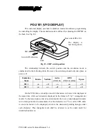
This customer display provides 4 emulation modes for software programming
in controlling the display. The emulation mode is defined by adjusting the DIP SW on
the back. See Fig. D-1.
Fig. D - 1 DIP switch position
The relationship between the switch position and the emulation mode is
summarized in the following table. However, the switching should only take place at
power off.
Emulation
Mode
Futaba
Noritake
Aedex
(PD2101)
ADM
(PD2101ADM)
Epson
SW 1
on
off
on
on
off
SW 2
on
on
off
off
off
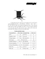
On the VFD, there are totally at most 40 characters in 2 rows to be displayed at
the same time, while each character displayed in the format of 5 by 7 rectangular dot
matrix. To the lower right corner of each dot matrix there are a round shaped dot and a
tail to form period and comma marks. For the characters in 2
nd
row of the VFD, there
is one more feature to be displayed, which is the downward pointing triangle under
each character. This triangular mark shall be referred to as the under mark for
identification later on.
SW2
SW1
Switch ON direction
Rear side of PD-2101
The display is
now facing down
Содержание PST-6000 SERIES
Страница 1: ...TM Rev A L 1 L 0 L P L 2 L 3 L 4 L 1 L 0 L P L 2 L 3 L 4 PST 6000 SERIES TECHNICAL MANUAL ...
Страница 8: ...vi TM ...
Страница 20: ...PST 6000 series Technical Manual 2 10 TM ...
Страница 22: ...PST 6000 series Technical Manual 3 2 TM ...
Страница 58: ...PST 6000 series Technical Manual 5 28 TM ...
Страница 73: ...PST 6000 series Technical Manual 7 3 TM DWG 2 Unscrew the bottom ...
Страница 74: ...PST 6000 series Technical Manual 7 4 TM DWG 3 Lifting the keyboard unit DWG 4 Taking the cable stoppers out ...
Страница 77: ...PST 6000 series Technical Manual 7 7 TM DWG 7 Cable connections inside PST system ...
Страница 82: ...PST 6000 series Technical Manual 7 12 TM ASSEMBLY DRAWING ...


