KS-6810 series Technical Manual 38
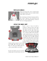
the 2 hooks on front cover that are arrowed in the above left picture before making
cable connections and closing the back cover assembly down.
TOP MOUNT UPGRADE KIT
Turn the top cover assembly that is left on the desktop
after taking away the system back cover assembly in the
way that the top edge is now away from you and it
appears like the picture at right.
The top mount MSR
option is installed in
the top edge inside the
front cover with its
control
board
indicated in the left
picture. Each item are
labeled and illustrated
below. Please note that the type of MSR control board determines the interface used
for MSR reader and the upper one of the MSR fixing screw is used also for
connecting the ground wire to the LCD bracket.
a.
MSR reader head (a dummy MSR if no MSR installed)
b.
MSR fixing screw
c.
MSR control board (SD-300D for USB interface or SD-420A for PS/2 interface)
d.
MSR control fixing screw
e.
Cable from MSR reader head
f.
Cable to main board
g.
Grounding wire
RELEASE FRONT BEZEL
a
b
c
d
e
f
d


