


KS-6215 / KS-6215I / KS-6217 series Technical Manual 6 - 2
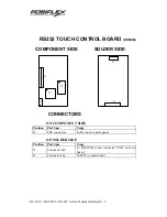
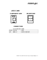
SOLDER SIDE
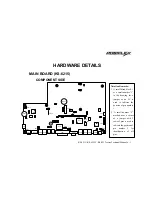
Notation Remarks:
1. A small black block
A
or a small number “1” in the drawing for a jumper or an IC is used to indicate the position of pin
number 1.
2. A small number “2” marked near a corner of a jumper with 2 rows of pins is used to indicate the position of pin number
2 for identification of all pins.
SODIMM1
1
U7
U9
F14
U8
Service window details
JP12
JP10
JP21
2
J5
2
JP17
2
JP20
2
JP11
2
JP13
The orientation of JP13 above is for
rev. C only. In rev. D it is as below:
JP13
Содержание Jiva KS-6215 Series
Страница 16: ...KS 6215 KS 6215I KS 6217 series Technical Manual 2 4 ...
Страница 36: ......


