© Latham Pool Products, Inc. 201
9
. All rights reserved.
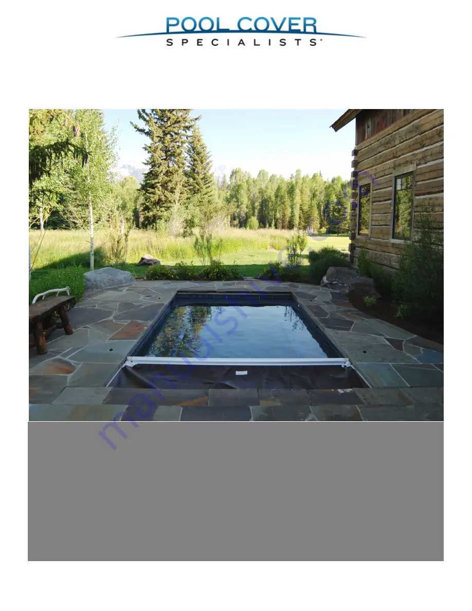
Mini Infinity 2 System
Automatic Safety Cover
Recessed Top Track Installation Guide
Страница 1: ... Latham Pool Products Inc 2019 All rights reserved Mini Infinity 2 System Automatic Safety Cover Recessed Top Track Installation Guide ...
Страница 2: ...rill or rotary hammer 2 Masonry drill bit 1 4 x 6 1 4 x 12 bit 3 Extension cords 4 2 and 3 Phillips standard screw drivers 5 Ratchet with 5 16 3 4 sockets Hacksaw 7 String line 8 Utility knife 9 Broom 10 Hammer rubber mallet 11 Pliers standard needle nose channel lock 12 Files round triangular flat 13 Lighter 14 Carpenter s square 15 5 16 hexheaddriverbitwith12 extension 16 Drill cordless or corde...
Страница 3: ...24 33600 10 x 1 Red Holob Anchor 25 26 H0276 Nut Nylock 1 4 20 27 H0501 Bolt HHMS 5 16 18 x 1 28 33226 5 16 Lock Washer 29 33356 1 4 20 x 5 8 Phillips Pan Head 30 33213 1 4 x 5 8 Washer 31 H0152 Screw PPMS 10 32 x 1 32 H0313 Screw HHWSM tek 10 x 1 2 SS 33 E1086 Bonding Lug Copper L35 34 24004 2009 T Slot Bolt Lock 35 H0512 Nut 5 16 18 36 33248 12 x 1 1 2 Phillips Pan Head Screw 37 H0310 Screw PPSM...
Страница 4: ...STANDARD TOP TRACK Step By Step Instructions Page Step Step by step installation instructions 5 1 Latham Pool Products Inc 2019 All rights reserved 4 of 20 ...
Страница 5: ...t is recommended that red chalk not be used as it is difficult to clean off the pool deck 1 2 3 4 5 8 Continue tapping the end of the track until the two sections of track are tight together so there is no gap between the lengths of track Before securing the track to the pool deck run the ropes through the track Position the cover track along both sides of the pool The lengths widths and diagonal ...
Страница 6: ... By Step Instructions RECESSED HORIZONTAL TRACK SLIM FLUSH TRACK Components Installation Guidelines Page System components Installation guidelines 7 Latham Pool Products Inc 2019 All rights reserved 6 of 20 ...
Страница 7: ...1531 for Recessed Horizontal Track b Mounted on top 2 x 4 stakes which are left in the deck permanently Attach housing to the stakes with self tapping screws or by drilling holes in the housing and using drywall or deck screws c Set into piles of concrete or gunite approximately every 4 feet If this method is used care must be taken to make sure that no cement is left higher than the bottom of the...
Страница 8: ...age Step Assembling the mechanism 9 1 Installing the mechanism in the cover box 9 6 Wiring the Touch Pad Control Switch 11 Electrical Wiring and Bonding 11 Latham Pool Products Inc 2019 All rights reserved Step By Step Instructions 8 of 20 ...
Страница 9: ... roll up tube should be set as high as possible without allowing the cover rub on the lid brackets Installing the Mechanism in the Cover Box Line up the mechanism with the track so the rope will come straight out and around the motor end pulley Center the tube in the cover box Tip If the pool is not square square up the mechanism with the track Attach the mechanism feet to the floor of the cover b...
Страница 10: ...ackets 12 18 Loosen the bolts on the adjustable brackets on the non motor end of the mechanism Spread the pulley brackets outward against the walls of the cover box Anchor the motor mechanism brackets into the cover box in as many places as possible Use the appropriate screws and anchors depending on the type of cover box being used On the motor and non motor side use the half inch screws 31 and n...
Страница 11: ...4 long should likewise be bonded to the mechanism There should be a bond wire from the equipment pad inside the cover box Attach this bond wire to the mechanism to complete the bonding requirement Note Builder is responsible to bring proper electrical lines conduit and bonding to the mechanism Electrical wiring diagram and details are shown above with instructions on the right Wiring The Electrica...
Страница 12: ...g the rope through the Track 13 4 Routing the Ropes 13 9 Installing the Positive Stop 14 17 Attaching the Leading Edge 16 28 Attaching the Ropes to the Reels 17 30 Pinning the Cover to the Tube 17 32 Latham Pool Products Inc 2019 All rights reserved Step By Step Instructions 12 of 20 ...
Страница 13: ...ld this portion of rope and pull the rope along the length of the track toward the end of the pool Turn the track back over Feed the rope through the pulley cartridge assembly 12 Insert the pulley assembly 12 onto the end of the track Pull the rope all the way to the cover box end of the track Alternate Rope Feeding Method Another common method of running rope in the track is to pierce the rope wi...
Страница 14: ...tical pulley on the front wall of the cover box 10 12 13 14 15 16 17 18 Run the rope from the non motor end along the backside of the cover box The rope should run through the rope loops 23 to keep it from getting caught in the cover Space the rope loops evenly across the back of the cover box Remove the guide from the end of the track Position the positive stop plate 49 over the track so that it ...
Страница 15: ... in the positive stop should line up with the holes in the cover Slide the Stop Plate Support Splice 48 into the track Line up the holes in the support splice with the holes in the track 24 25 Use a drill with a 5 32 hex bit to tighten the 4 hex head screws in the stop 26 Insert the wheel assembly 7 into the lead ing edge 27 Drill a minimum of three pilot holes evenly spaced around the leading edg...
Страница 16: ...f the leading edge Do not drill through the cover Insert a 10 x 1 2 screw 37 to pin the cover to the leading edge 28 29 30 31 32 33 35 34 36 Drill a hole using a 3 16 bit in the flat section of the leading edge just behind the rope channel This is where a bonding lug will be attached Do this on both ends of the leading edge tube Connect the bonding wire that is attached to the front corner of the ...
Страница 17: ...h ropes tight use a lighter or torch to burn the rope in the location it will be cut This will help them not fray after they have been cut Cut the ropes so they are at least 8 ft long Use the lighter to burn the cut ends of the rope if needed Find the center of the slack and pin directly to the tube DO NOT FOLD THE SLACK Repeat this step several times along the tube Tip Use the weld line on the tu...
Страница 18: ...just Current Limits The touch pad retrofit model supports electronic current limiting The default current settings are 7 5 Amps The system will actively monitor operation of the cover and stop the system if current exceed 150 of the above value To adjust these settings do the following 1 Access the service menu using the service passcode 5991 2 Press the Service button The display will alternate b...
Страница 19: ...portant to instruct the home owner on how to operate the cover system safely and do routine maintainence Use the following check list and the homeowner guide as your primary instruction sources Latham Pool Products Inc 2019 All rights reserved Step By Step Instructions 19 of 20 ...
Страница 20: ...ake sure there is adequate drainage from the cover box Cover q Fabric pinned to the roll up tube without pinned folds q Cover runs smoothly q Cover properly aligned when it closes or retracts Note An inch or two out of square is not uncommon and is not a concern as it will not effect the operation of the cover Because of the size of the fabric roll and changes in operating conditions the cover may...