


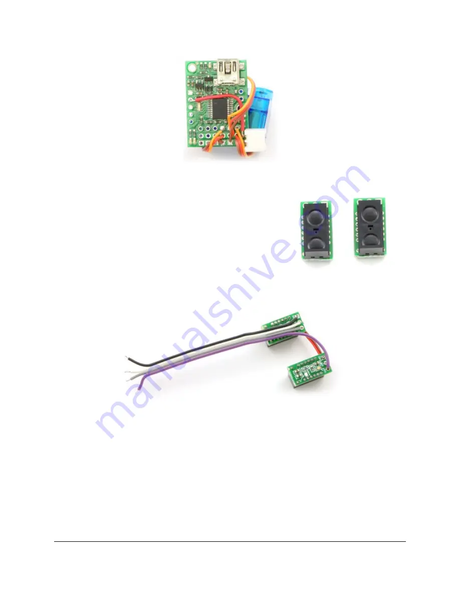
Digital distance sensors with
trimmed carrier boards.
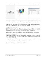
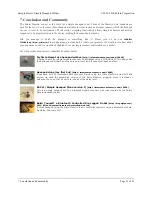
Connecting the servos to ports 0,
1, and 2 on the Micro Maestro.
Cut the sensor boards with a rotary tool, grinding wheel, diagonal cutters,
or a jeweler’s saw, removing the part containing the unneeded mounting
hole, so that they are as small as possible. (Make sure you do not cut any
traces.) Then solder them to a cable so that you can connect them to the
Maestro. The example below uses a 4-wire ribbon cable, sharing the
power and ground connections for the two sensors. Ribbon cable makes
the assembly relatively clean, but you can use whatever wire you have
available. Look ahead in the instructions to see where the sensors are
going to go, and make sure that you have a long enough cable. Think
about how to keep the wires close to the body and out of the way of the
legs and servos.
Soldering the sensors to a four-pin cable.
Solder the sensor power and ground to +5V and ground on the Maestro, and connect the outputs of the right and
left sensors to channels 3 and 4, respectively. Note that we use +5V instead of the battery voltage so that the
Maestro channels will never see higher voltages – and another benefit is that the sensors will work under USB
power, without the battery plugged in.
Sample Project: Simple Hexapod Walker
© 2001–2010 Pololu Corporation
3. Construction
Page 8 of 21