- 14 -
2000_DE_Anbau_293
EN
ATTACHING TO TRACTOR
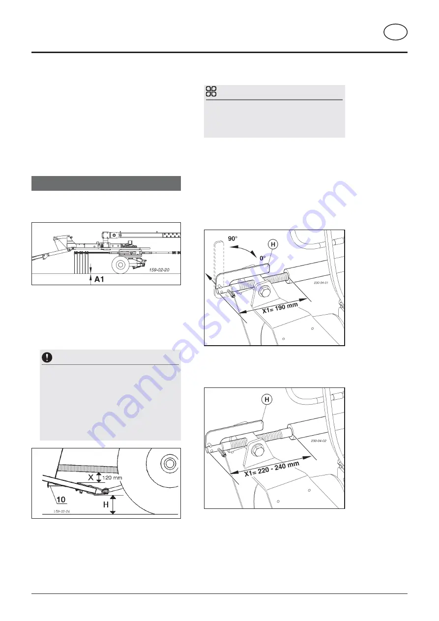
4. Adjusting rake height
TIP
The rake height dependent on the tractor and mount-
ing angle of the device. Reset the rake height if you
change tractors or alter the distance between the
cardan shaft and the toolbar.
Set the rake height
(X1)
with the threaded spindle
depending on whether or not the device is fitted with
"Multitast".
The machine is connected to the tractor and in headland
position (see above)
1. Swivel the lever (H) upwards (90°)
2. Loosen lock nut
3. Set the working height on the threaded spindle
a. Machines without "MULTITAST": X1 = 190 mm
Turn the threaded spindle until the thread is directly
aligned with the cylinder
a. Machines with "MULTITAST": X1 = 220 - 240mm
Twist the threaded spindle at a distance from the cylinder
4. Swivel down the lever (H) (0°)
5. Tighten the locking nut
In this position (0°) the threaded spindle is secured against
twisting.
Cutting to length procedure
- To adapt the lengths, hold cardan shaft halves next
to one another in the shortest operating position (L2)
and mark.
Shortest possible operating position (L2):
1. Lower hoist completely
2. Steering turned to lock.
(see adjacent illustration)
For details see chapter "Adapting the PTO shaft".
Preparations for initial use
1. Put the machine in the working position.
The working position is when the device is lowered and
the ground clearance of the tines (A1) is 10 mm - 0 mm.
2. Check the distance between the cardan shaft
and the toolbar
The distance (X) between the cardan shaft and the
toolbar must be sufficient to prevent collections between
the cardan shaft and the toolbar!
General standard gauge: 120mm
NOTE
Material damage in the event of a collision between
cardan shaft and toolbar.
If the terrain is extremely uneven, it is possible that
the general standard gauge (measured on a level
surface) may not be sufficient to prevent a collision.
Check the distance between the cardan shaft and the
toolbar at topologically sensitive points (e.g. round
ends) and adjust if necessary.
3. Check the position of the rotor tines
The position of the rotor tines (A1) should be somewhat
parallel to the ground; less inclination to the front is
permitted.


