PMD PMDX-132 Скачать руководство пользователя страница 15

PMDX-132 User’s Manual

PCB Revision: PCB-466A

Document Revision: 1.0

Serial Numbers: 23410 and above

PMDX-132_Manual_10.doc

©2008 Practical Micro Design, Inc.

Page 15 of 24

17 April 2008

All Rights Reserved

The PMDX-132 provides its own isolated power for the status inputs (see sections 3.4 and 4.6) and
control outputs (see sections 3.2 and 4.7).  Therefore, the AC power supply does not require an external
isolation transformer.
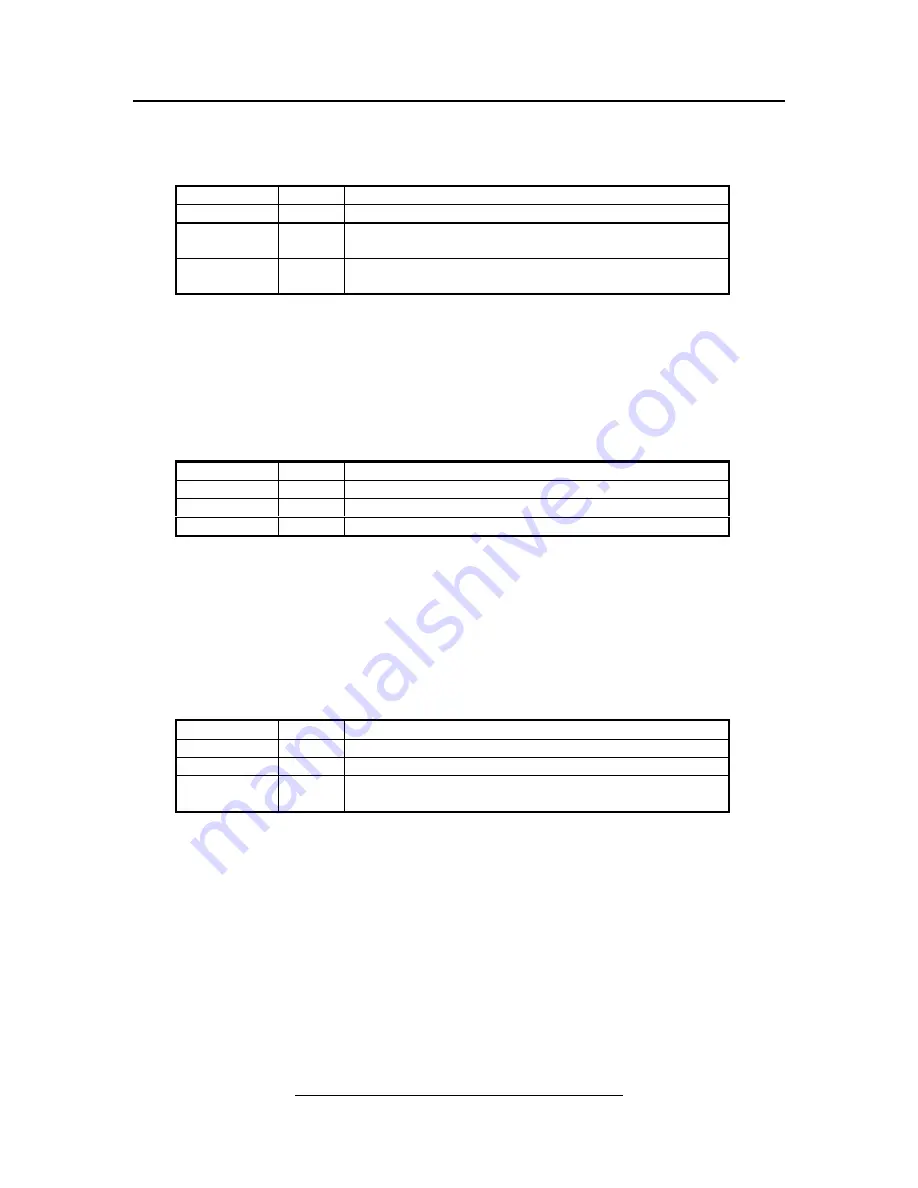
Pin Number

Label

Description

1

0V

Connection for AC mains NEUTRAL input

2

120

VAC

Input for use with 120 VAC mains
(leave as a “no connect” for 240 VAC mains)

3

240

VAC

Input for use with 240 VAC mains
(leave as a “no connect” for 120 VAC mains)

Table 4 – AC Power Connector Pin-Out (J2)

4.3 

Relay Contact Connectors (J3 & J4)

J3 and J4 provide connections to the output relay contacts.  These contact ratings are specified in section
7.0.  These relays may be controlled by two of the control signals, or they may be disabled, depending on
the configuration of jumpers JP3 and JP4 (see section 5.3).

Pin Number

Label

Description

1

N/O

Normally open contact

2

COM

Common center pole

3

N/C

Normally closed contact

Table 5 – Relay Contact Connector Pin-Out (J3 and J4)

4.4 

Unregulated Power and Daisy-Chain Output (J5)

The PMDX-132 provides an unregulated 12 to 16 volt DC power output on J5.  This output can be used
to power a fan (24 volt fan running “under speed” is recommended), or to power a companion
PMDX-122 board.  Note that this power output (and therefore any connected PMDX-122 boards) share
ground with the PC side of the interface isolation barrier.

Pin Number

Label

Description

1

chain

Fault signal output, used to daisy-chain to a PMDX-122

2

fan pwr

Unregulated power output for fan or PMDX-122

3

PC side

ground

Ground reference on PC side of the isolation barrier

Table 6 – Unregulated Power and Daisy-Chain Connector Pin-Out (J5)

4.5 

PC Parallel Port (J6 & J7)

The PMDX-132 provides a Centronics-style connector (J6) for connections to a PC’s parallel port.  This
allows the use of a standard PC printer cable.  The board also provides a 26-pin ribbon cable header (J7).
This header allows the use of a “ribbon cable to 25-pin “D” connector” adapter cable as an alternative to
the standard PC printer cable and the Centronics connector, or a ribbon cable to devices with a
compatible ribbon connector such as the SmoothStepper.

Содержание PMDX-132

Страница 1: ...rved PMDX 132 4 Axis Breakout Motherboard for Gecko Stepper Motor Drivers User s Manual Document Revision 1 0 Date 17 April 2008 PCB Revision PCB 466A Serial Numbers 23410 and above PMDX Web http www...

Страница 2: ...10 3 5 1 Fault Input 11 3 5 2 E Stop Input 12 3 5 3 Motor Disable Input 12 3 6 Charge Pump watchdog 12 4 0 Connectors 13 4 1 DC Motor Power Supply J1 14 4 2 AC Power Supply J2 14 4 3 Relay Contact Con...

Страница 3: ...o which the PMDX 132 is installed should provide fail safe protection and emergency stop capability The PMDX 132 contains circuitry that may be connected to dangerous voltages Care must be taken that...

Страница 4: ...drivers Special Features Pluggable wire clamp terminal strips for I O connections from parallel port status and control signals Support for charge pump Auxiliary 5V supply output Power output for opt...

Страница 5: ...et resistor in the corresponding 2 pin terminal strip on the PMDX 132 When looking at the PMDX 132 Geckodrive assembly from the edge as shown in Figure 1 this would be the green 2 pin terminal strip a...

Страница 6: ...11 of the PC s parallel port When the LED is interrupted the transistor stops conducting and the PMDX 132 s pull up resistor gives a logic high on pin 11 The same basic operation applies to the refle...

Страница 7: ...ormal signal only pin2 pin3 COM pin4 pin5 COM pin8 pin9 COM pin6 pin7 COM RLY COM N C N O J1 J2 J3 J4 J7 J8 J5 J6 J10 J9 GND GND pin11 5V AUX OUT pin12 pin13 pin15 fault E Stop GND PWR Alt In pin17 pi...

Страница 8: ...the charge pump circuit See sections 3 5 and 3 6 for more information Figure 4 Block diagram of data bus step and direction signals 3 2 Control Outputs The control signals are isolated and buffered by...

Страница 9: ...gnators See section 5 3 for more information on the jumper settings Each relay driver circuit has its own LED in addition to the LED on the control output section as described in section 3 2 The relay...

Страница 10: ...input signal is driven low The optical isolators further act as a low pass filter to remove high frequency noise from the inputs NOTE Due to logic inside the PC some status inputs are inverted This m...

Страница 11: ...rcuitry and Table 1 on page 11 shows the effects of the Fault signal The Fault input can be connected to an external wired or configuration of open collector status signals or mechanical switches to g...

Страница 12: ...e LED labeled Outputs Enabled reference designator DS12 along the right hand edge of the board is off The Fault daisy chain output on J5 is tri stated with a weak 10K ohm pull down The control outputs...

Страница 13: ...arge pump circuit see section 5 1 See section 7 0 Electrical and Environmental Specifications for information on minimum charge pump frequency NOTE The state of the charge pump signal is not reflected...

Страница 14: ...cate the presence of DC power Pin Number Label Description 1 POS Positive DC input terminal 2 NEG Negative DC input terminal does not have to be the same as the PC s ground reference Table 3 DC Power...

Страница 15: ...ct 2 COM Common center pole 3 N C Normally closed contact Table 5 Relay Contact Connector Pin Out J3 and J4 4 4 Unregulated Power and Daisy Chain Output J5 The PMDX 132 provides an unregulated 12 to 1...

Страница 16: ...in Contact Closure pin 11 12 12 23 Paper End in Contact Closure pin 12 13 13 25 Select Out note 4 in Contact Closure pin 13 Isolated and buffered signals into PC with internal pull up resistors allow...

Страница 17: ...tions for all of the PC parallel port status signals except for pin 10 Pin 10 is used to indicate emergency stop and fault conditions to the PC See section 3 5 2 for more information on the emergency...

Страница 18: ...drivers may be installed on these sets of connectors in any combination The only restriction is that the step and direction signals from the PC s parallel port are hard wired to specific connectors as...

Страница 19: ...tion opto couplers Your Gecko stepper drivers should be jumpered for 5VDC common if equipped with a jumper The Gecko 201 and 202 drives do not have such a jumper and are always configured for 5VDC com...

Страница 20: ...data bus and control signals Figure 10 on page 20 shows the location of this jumper Setting Label Description 1 to 2 not Estop Outputs will be enabled whenever an emergency stop or fault condition do...

Страница 21: ...ect whether the PC parallel port signals control the two relays or the relays are not used Figure 10 on page 20 shows the location of these jumpers Setting Label Description 1 to 2 pin 1 Relay control...

Страница 22: ...this far depending on model The height between the bottom of the Gecko drivers and the bottom of the PMDX 132 circuit board is 1 25 This allows mounting the circuit board on standard 1 25 tall by 0 25...

Страница 23: ...above 5 amperes even when setting the Gecko stepper drivers for motor currents above 5 amperes The Gecko stepper drivers will draw less than 5 amperes even when providing more than 5 amperes to the mo...

Страница 24: ...re limited to 90 days from the date of purchase and no warranties expressed or implied will apply after that period All warranties for this product expressed or implied shall extend only to the origin...

Отзывы: