


PMDX-132 User’s Manual
PCB Revision: PCB-466A
Document Revision: 1.0
Serial Numbers: 23410 and above
PMDX-132_Manual_10.doc
©2008 Practical Micro Design, Inc.
Page 13 of 24
17 April 2008
All Rights Reserved
and the CAD/CAM application software is running). It does this by monitoring pin 17 on the PC parallel
port. When this signal is toggling between high and low, the charge pump is “OK”. When pin 17 stops
toggling, the charge pump is “not OK”. Jumper JP1 determines whether the output from the charge pump
is used to enable and disable the control and data bus output buffers (see section 5.1). See Table 1 on
page 11 for a summary of the effects of the charge pump circuit.
This charge pump circuit is designed to work with any software that can toggle pin 17 on the PC parallel
port. If your software does not support this feature, configure jumper JP1 to disable the charge pump
circuit (see section 5.1). See section 7.0,
Electrical and Environmental Specifications
, for information on
minimum charge pump frequency.
NOTE –
The state of the charge pump signal is
not
reflected in the
E-Stop
and
Fault
status that
is output on pin 10 to the PC. This is to prevent “lock up” of the software. Mach2/3
CNC software requires that the Emergency Stop signal
not
be asserted before it will
start generating the “charge pump” signal.
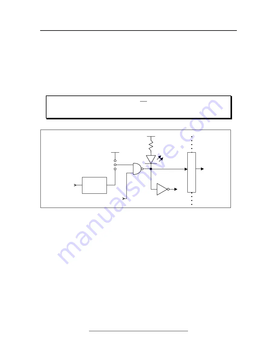
Figure 9 – Block Diagram of Charge Pump signals
4.0 Connectors
The PMDX-132 contains the following connectors. Refer to the following sections for details on the pin-
outs for each connector. For all connectors, pin “1” is the pin closest to the reference designator (i.e. J1
pin 1 is the pin closest to the “J1” text on the circuit board). In addition, all connectors have square pads
on pin 1 (look on the bottom of the circuit board).
2
1
3
JP1
+5V
Isolated Pin 17
(from Control
Signal Input)
Charge
Pump
OK
OK (isolated)
(to Data Bus
enable)
I
S
O
L
A
T
E
EStop/Fault*
(from EStop/Fault)
CP-OK
not EStop
2.2K
+5V
(to control
buffer enable)


