Installation manual SR85
2.5 Interface
1.
Change EPROM on the Main board PCB1 in the printer finisher.
2.
Remove the printer finisher connectors CN115, CN120 and CN125 from the Main
board PCB1.
3.
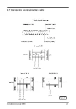
Take the Communication cable from the installation kit.
Note, make sure you
connect the connectors correctly, the yellow wire should always be on
top, figure 12.
Connect connectors CN115, CN120 and CN125 on the Main board
PCB1.
4.
Connect the printer finisher connectors CN115, CN120 and CN125 to the harness.
5.
Secure the harness in the finisher with tie raps from the installation kit.
2-7
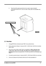
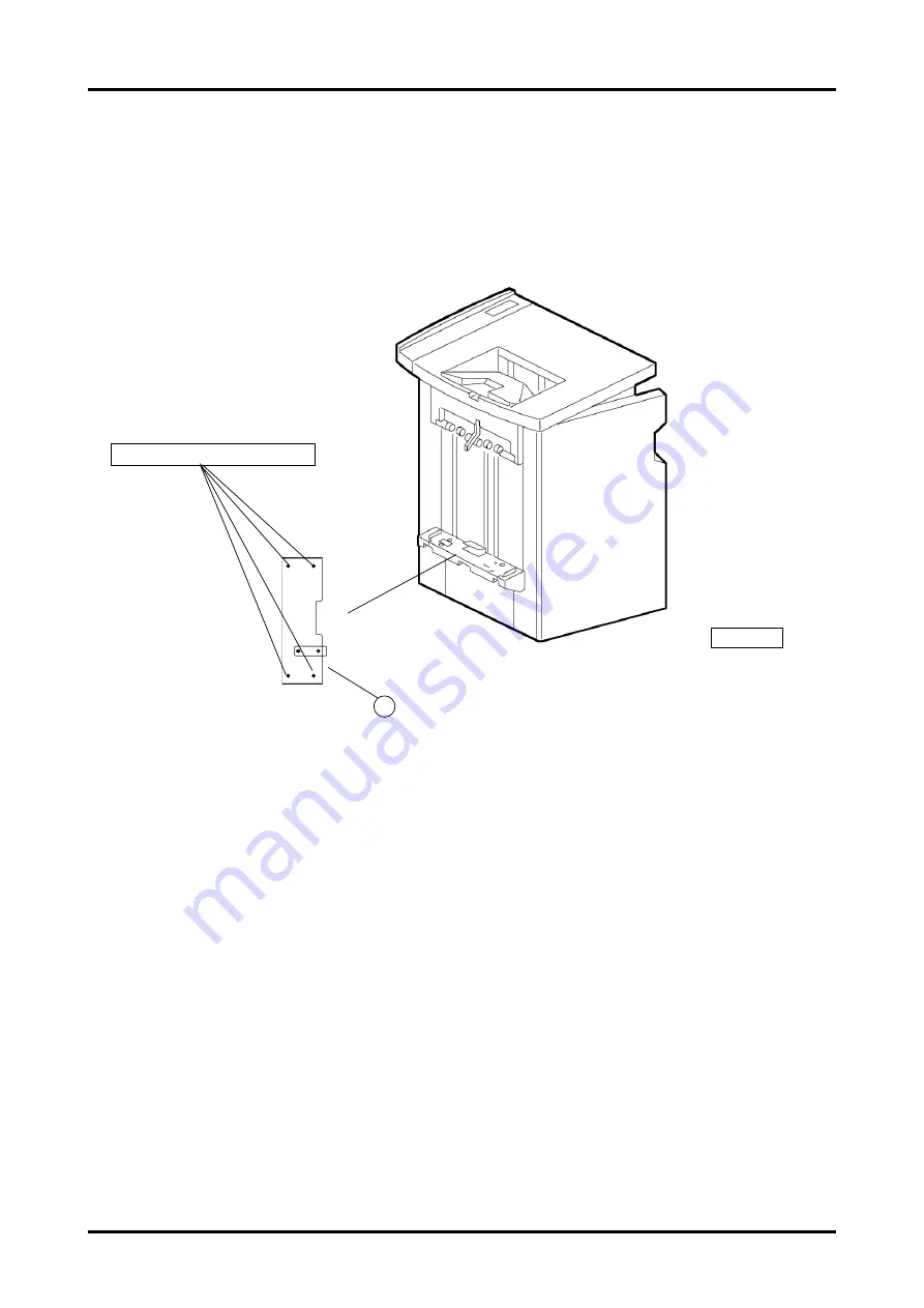
Four 5.5 mm counter screws
Figure 10
2
8.
Take the shift tray plate (2) with the four counter holes and install it
on the printer with four 5.5 x 6 mm counter screws (from the installation kit),
figure 10.
Содержание SR 85
Страница 1: ...Installation Manual Bookletmaker SR 85 and Trimmer TR 85 January 2002 x17030 ...
Страница 12: ...Installation manual SR85 Figure 11 2 6 Wiring communication cable 2 8 ...
Страница 13: ...Installation manual SR85 2 7 Connectors communication cable Figure 12 2 9 ...
Страница 20: ...Installation manual SR85 2 3 4 7 2 Figure 17 3 4 10 11 9 1 1 6 8 ...

