background image

6. QoS Configuration 

Allow user to enable the QoS function and configure. This function is explained in section 3.2.8. 

7. Bandwidth Control 

Allow user to enable the bandwidth control function and configure. This function is explained in section 3.2.9. 

8. Misc Configuration 

Allow user to configure the advanced function. This function is explained in section 3.2.10. 

9. PoE Configuration 

Allow user to configure the Power over Ethernet function. This function is explained in section 3.2.11.       

0. Logout 

Allow user to logout the Switch console interface. This function is explained in section 3.2.12. 

3.2.3 Port Status 

Press 1

 on your keyboard or use the 

"Tab" 

key to move the highlight to the Port Status and press 

"Enter"

 to access the 

screen of

 Port Status

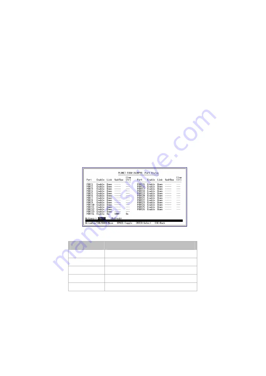
 from the Main Menu screen (please see the figure3-4). The screen of Port Status in figure 3-5 appears. 

Table 3-2 describes the Port Status objects of Switch. This menu allows you to view the port status of the Switch. 


Figure 3-5

 Port Status Screen 

Object 

Description 

Port 

Indicate port 1 to port 24, and 2-module slot. 

Enable 

Display disable or enable on each port. 

Link 

Display current link status on each port. 

Spd/Dpx 

Display current speed duplex mode on each port. 

Flow Ctrl 

Display current flow control status on each port. 

Table 3-2

 Descriptions of the Port Status screen Objects 

Содержание FGSW-2402PVS

Страница 1: ...24 Port 10 100Mbps 2 Gigabit Web Smart PoE Switch FGSW 2402PVS FGSW 2620PVS FGSW 2612PVS User s Manual...

Страница 2: ...s Manual and or to the products described in this User s Manual at any time without notice If you find information in this manual that is incorrect misleading or incomplete we would appreciate your c...

Страница 3: ...FIGURATION 12 3 1 Preparing for configuration 12 3 1 1 Connecting a PC or Terminal to the RS 232 Port 12 3 1 2 Terminal Emulation Setup Program 12 3 1 3 Power up Self test Status 13 3 1 4 Login 13 3 2...

Страница 4: ...ord Setting 46 4 10 3 Reset System Default Setting 48 4 10 4 Reboot System 48 4 10 5 System Information 49 4 10 6 IP Configuration 49 4 11 PoE Configuration 50 4 11 1 POE Ports 50 4 11 2 PoE Ports Sta...

Страница 5: ...Gigabit Web Smart Power over Ethernet Switch User s Manual is structured as follows Section 2 Installation It explains the switch functions and how to physically install the Switch Section 3 Console...

Страница 6: ...onsole and Web interface for Switch basic management and setup Support up to 26 port based VLAN groups Support up to 7 Trunk groups each trunk for up to maximum 4 port with 800Mbps bandwidth Port mirr...

Страница 7: ...port per trunk VLAN 26 Port based VLAN groups Port Mirroring 1 Mirroring port to monitor several mirrored ports The monitor modes are Disable RX TX TX RX QoS Allow to assign low and high priority on...

Страница 8: ...Mirroring QoS bandwidth control Misc Configuration 2 1 1 Product Overview The Switch are web smart fast Ethernet switch which with IEEE802 3af Power over Ethernet power injector built in Except 24 RJ...

Страница 9: ...stablished Blink indicate that the switch is actively sending or receiving data over that port 100 Orange Light indicate that the port is operating at 100Mbps Off indicate that the port is operating a...

Страница 10: ...ocedures in the order being presented To install your Switch on a desktop or shelf simply complete the following steps 2 2 1 Desktop Installation To install a Switch on a desktop or shelf simply compl...

Страница 11: ...4 shows how to attach brackets to one side of the Switch Figure 2 4 Attaching the brackets to the Switch Caution You must use the screws supplied with the mounting brackets Damage caused to the parts...

Страница 12: ...reparing for configuration 3 1 1 Connecting a PC or Terminal to the RS 232 Port When you are ready to configure the smart functions of the Switch make sure you had connected the supplied RS 232 serial...

Страница 13: ...enu of the Power up System Self diagnostic Process Figure 3 2 Power up System Self diagnostic screen 3 1 4 Login After the self test completes successfully the screen in figure 3 3 appears Login is re...

Страница 14: ...d use the Tab key to choose the Save for save the current configuration You can also choose each function through press the value 0 9 on your keyboard Please refer to figure 3 4 for available options...

Страница 15: ...explained in section 3 2 12 3 2 3 Port Status Press 1 on your keyboard or use the Tab key to move the highlight to the Port Status and press Enter to access the screen of Port Status from the Main Men...

Страница 16: ...the current configuration Figure 3 6 Port Configuration Screen Object Description Port Indicate port 1 to port 24 and 2 module slot Enable Display disable or enable on each port Link Display current l...

Страница 17: ...speed trunk Use the Tab key to choose the Edit and press Enter Then start to modify these settings Use the Tab key to move the highlight to the selection and press the Space Bar key to toggle back an...

Страница 18: ...3 5 Descriptions of the Trunk Configuration screen Objects 3 2 6 1 Create a Port Based VLAN Group Choose Port Based from the VLAN mode of VLAN Configure The screen in figure 3 9 appears with message...

Страница 19: ...he Tab key to move the highlight to the Edit and press Enter to modify these settings Use the Tab key to move the highlight to the selection and press the Space Bar key to toggle back and forth betwee...

Страница 20: ...N Configuration screen The screen in figure 3 16 appears Figure 3 16 Create a port based VLAN Group completed screen 3 2 6 2 Edit a VLAN Group Use the Tab key to move the highlight to the Edit and pre...

Страница 21: ...ve for saving the current configuration The screen in figure 3 19 appears with message Operation completed successfully Figure 3 19 Save VLAN Configuration successfully screen 3 2 6 3 Delete a VLAN Gr...

Страница 22: ...LAN Group Screen After press Y The screen similar to figure 3 23 appears with message Operation completed success fully Figure 3 23 Delete existence VLAN Group successfully Screen Figure 3 24 Delete e...

Страница 23: ...nd forth between the options The screen of Port Mirroring Configuration in figure 3 26 appears Figure 3 26 Port Mirroring Configuration Screen Object Description Port Monitoring Mode The available opt...

Страница 24: ...High Low 5 1 High Low 7 1 and High empty then Low selection from QoS mode Use the Tab key to choose the Edit and start to modify these settings Use the Tab key to move the highlight to the selection a...

Страница 25: ...descriptions of the Bandwidth control screen Objects Use the Tab key to choose the Edit and start to modify these settings The screen of Bandwidth control in figure 3 30 appears Figure 3 30 Bandwidth...

Страница 26: ...rd Maximum up to 8 characters Please refer to chapter 3 2 10 2 Reset System Default Setting Allow user to reset the Switch to default mode Please refer to chapter 3 2 10 3 Reboot System Allow user to...

Страница 27: ...ble The available options are Disable 150 sec 300 sec and 600 sec The default is 300sec MAC Table Hashing The available options are CRC Hash and Direct Map Console Auto Logout Time Allow user to set t...

Страница 28: ...The available options are CRC Hash and Direct Map Password Again Input the password again to confirm Table 3 12 Descriptions of the Password Setting screen Objects After setup is complete press Esc ke...

Страница 29: ...3 39 appears After power on completed then the login screen in figure 3 40 appears Figure 3 39 Reboot Switch Screen Figure 3 40 Switch Console Login Screen 3 2 10 4 Reboot System Press 4 on your keyb...

Страница 30: ...gure 3 43 appears Figure 3 41 Reboot System Screen Figure 3 42 Switch Reboot Screen Figure 3 43 Switch Console Login Screen 3 2 10 5 System Information Press 5 on your keyboard or use the Tab key to m...

Страница 31: ...dify IP address Allow user to modify the IP address of the Switch The default IP address is 192 168 0 100 Subnet Mask Allow user to modify the Subnet Mask of the Switch Default Gateway Allow user to m...

Страница 32: ...iguration screen Objects The screen of POE Configuration in figure 3 49 appears Figure 3 49 POE Configuration Screen Object Description POE Ports Config Allow user to configure the POE function and po...

Страница 33: ...owest Table 3 15 Descriptions of the POE Ports Config screen Objects After setup is complete press Esc key to return to Actions menu and use the Tab key to choose the Save for saving the current confi...

Страница 34: ...The screen in figure 3 52 appears Then the main menu in screen figure3 53 appears Figure 3 52 Return to Main Menu Screen Figure 3 53 Main Menu Screen 3 2 12 Logout Press 0 on your keyboard or use the...

Страница 35: ...b interface 4 1 Login in to the Switch Before you start configure the Switch please note the Switch is configured through an Ethernet connection make sure the manager PC must be set on same the IP sub...

Страница 36: ...ion and configure Explained in section 4 6 Port Mirroring Configuration Allow user to enable the port mirroring function and con figure Explained in section 4 7 QoS Configuration Allow user to enable...

Страница 37: ...ection flow control disable enable of each port The screen is as figure 4 4 Figure 4 4 Port Configuration Screen After setup is complete press Apply button for save the current configuration The scree...

Страница 38: ...unk Configuration Screen After setup is complete press Apply button for save the current configuration The screen in figure 4 7 appears with message Operation completed successfully Figure 4 7 Trunk C...

Страница 39: ...o 26 port based VLAN groups can be added and the group ID range is 1 255 Figure 4 10 VLAN Configuration Screen After setup is complete press Apply button for save the current configuration The screen...

Страница 40: ...d to the Monitoring port RX TX This mode will duplicate the data send and receive from the Monitored port Forward to the Monitoring port with 1 1 ratio Table 4 1 Descriptions of the Port Mirroring Con...

Страница 41: ...n Low Forward the packets with high priority first then packets with low priority High Low 3 1 The packet output ration of high priority and low priority is 3 to 1 High Low 5 1 The packet output ratio...

Страница 42: ...18 QoS Configuration save successfully Screen Press Back for back to previous web screen 4 9 Bandwidth Control This function allows setting bandwidth on each port Table 4 3 shows the descriptions of t...

Страница 43: ...20 Bandwidth Control save successfully Screen Press Back for back to previous web screen 4 10 Misc Configuration This function provides the advanced configuration of the Switch The available options...

Страница 44: ...ation Screen 4 10 1 Advanced Switch Configuration The available options are shown as below Broadcast Strom Filter If this function enable the Switch will limitation the broadcast packets The available...

Страница 45: ...ble Hashing The available options are CRC Hash and Direct Map The screen in figure 4 25 appears Figure 4 25 MAC Table Hashing Screen Console Auto Logout Time Allow user to set the Auto logout time of...

Страница 46: ...s the descriptions of the Password Setting screen Objects Object Description Password protection Allow user to disable or enable the password request of the console and Web interface User Name Allow u...

Страница 47: ...witch Then can enter into the web interface of the Switch without any username and password request If enable the password protection Then the following screen appears Figure 4 31 Password Setting Scr...

Страница 48: ...Press Back for back to previous web screen 4 10 3 Reset System Default Setting This function allows resetting the Switch to default mode The screen in figure 4 33 appears Press OK then the Switch wil...

Страница 49: ...IP Configuration This function allows modifying the IP address subnet mask and default gateway The screen in figure 4 36 appears Note The default IP address is 192 168 0 100 Figure 4 36 IP Configurat...

Страница 50: ...t Status Allow user to check the port Power over Ethernet settings and the connected power usage Please refer to section 4 11 2 4 11 1 POE Ports This function allows Enable Disable POE function and se...

Страница 51: ...power usage The screen in figure 4 40 appears Figure 4 40 POE Ports Status Screen 4 12 Logout This function allows to logout the web interface of the Switch The screen in figure 4 41 appears Press OK...

Страница 52: ...packet will be filtered Thereby increasing the network throughput and availability 5 4 Store and Forward Store and Forward is one type of packet forwarding techniques A Store and Forward Ethernet Swit...

Страница 53: ...r Reset This is done by detect the modes and speeds at the second of both device is connected and capable of both 10Base T and 100Base TX devices can connect with the port in either Half or Full Duple...

Страница 54: ...t Solution Please check the VLAN settings trunk settings or port enabled disabled status Performance is bad Solution Check the full duplex status of the Ethernet Switch If the Ethernet Switch is set t...

Страница 55: ...net Switch to another switch a bridge or a hub a straight or crossover cable is necessary Each port of the Switch supports auto MDI MDI X detection That means you can directly connect the Switch to an...

Страница 56: ...s color coded The following shows the pin allocation and color of straight cable and crossover cable connection Figure A 1 Straight Through and Crossover Cable Please make sure your connected cables a...

Отзывы: