


15
14
DOC_NIP_CON_SMART_EN_20200619
DOC_NIP_CON_SMART_EN_20200619
EN
EN
It is not necessary to create a template for simple measurements.
The parameters for the measuring points can be entered directly.
The
Template Simple measurement
offers a good opportunity to
familiarize yourself with the software and the measurement process.
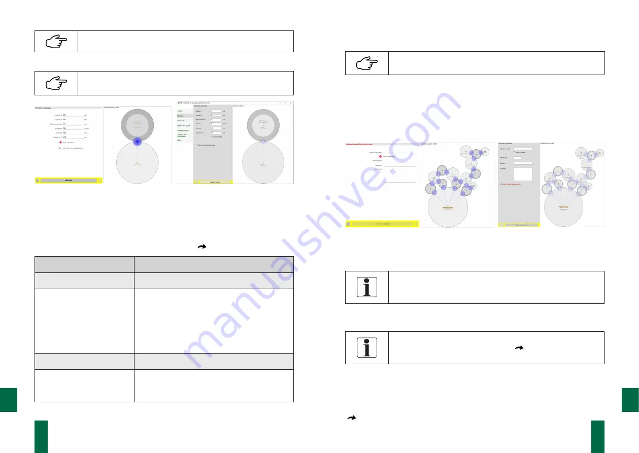
App
PC software
Fig. 4. Parameter input Template Simple measurement
Parameter
In addition to the roller parameters, the software also records set-point and tolerance
values for the contact strip width of the roller pairing. Additional information can be
stored by selecting
Ask other and save measuring.
(
Table of parameters
).
Measuring point parameters
Additional information
Roller parameters
Machine parameters
Diameter1
Machine number
Diameter2
Printing unit
Rubber thickness
Rubber hardness
Comparative values
Other
Setpoint NIP width
Operator
Tolerance range NIP width
Comment
Table of parameters
The parameter input is completed with the
Measure
or
Parameter and measure
button.
By activating
□
√
Save in template
, the entered values are perma-
nently assigned to
Template Simple measurement.
Template Roller Diagram
For complex measuring tasks e.g. the roller adjustment on entire printing units or
printing presses can be created with the help of the PC software and can be transfer-
red to the respective mobile device. This makes it possible to prepare a large number
of roller pairs in advance and to use the graphical representation to guide you
through the measuring process.
App
PC software
Fig. 5. Entering parameters for the roller diagram template
Machine parameters
The machine number and printing unit must be entered for assig-
ning the measured values to the template of the roller diagram.
This information cannot be changed later!
Additional information can be entered in the operator and comment field. The
parameter input is completed with the
Save and measure
button.
The parameters of the individual measuring points were already
created when the template was created (
Chapter 7.4.6 Create
Template)
on the PC.
7.3.2 Recording the Measured Values
After completing the parameter entry, the software changes to the measurement view.
The measurement view shows the list of all measurement points, the preview window
with the roller diagram and the measured value display of the current measured values
(
Figure 6 Measurement view).


