


33
32
DOC_NIP_CON_SMART_EN_20200619
DOC_NIP_CON_SMART_EN_20200619
EN
EN
Collected measurement data are saved on the tablet in the directory
... My Documents / Documents / NipCon /
(
Section 7.1.2 Tablet)
The software continuously scans the import directory and automatically sorts measu-
rement data by year, month and day (the time of measurement) in the directory
... / Public documents / NipCon / DataStore / Year / Month / Day
(archive).
7.4.6 Create Template
The
Simple Measurement
template is provided by the software after the program
starts.
In the
Create template
menu item, more complex tasks such as roller adjustments
on complete printing units or printing presses can be prepared. It is only available
on the PC. The starting point is the roller diagram of your printing press
You can find the roller diagrams of your printing press in the
corresponding documentation from the manufacturer.
Digitalization of the Roller Diagram
▬
Photograph or scan the roller diagram with as little distortion as possible.
Permitted image formats are *.jpg und *.bmp
▬
Move the image file to your PC.
The name of the image file defines the name of the template. Do not
use special characters or separators such as _ or - when renaming.
▬
If necessary, crop the image so that only essential information is retained.
To Create a Template:
▬
Open the image of the roller scheme
The action button
Open picture
in the template view starts
Windows Explorer and enables the selection of the image file of the
roller diagram from any directory.
The picture is shown in the drawing area. While holding down the
mouse button, the image can be moved or zoomed in and out
using the scroll wheel.
(
Section 7.4.3 Measure)
▬
Trace the circumference of all rollers.
Start with the largest roller of the machine or on the plate cylinder.
By setting 3 points along the circumference, the position and
diameter of the rollers are determined. After setting the 3rd point,
the roller is shown in the picture.
With the left mouse button, a point is set, with the right mouse
button the last set point is undone.
Blue connecting lines between the centers of the circles mark
contact points (possible measuring points), which now appear in
the template preview.
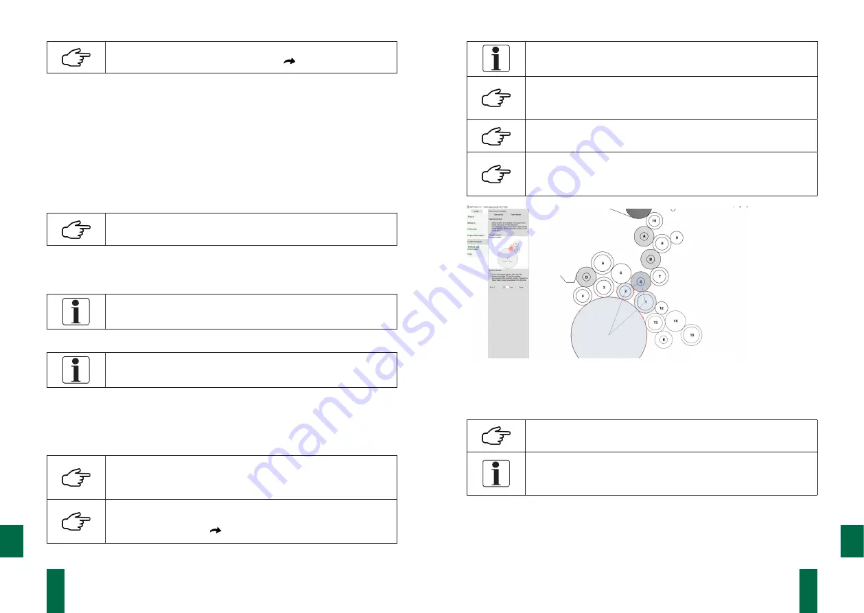
Fig. 20. Creation of a template, geometric representation
▬
Enter the roller diameter of roller 1 of the template.
▬
Use the action button Setup to save the template.
The template file with the same name as that of the picture is
saved
(„PictureName“.txt)
.
The saved template file is incomplete with regards to the roller
parameters and cannot yet be used for measurement purposes. It
is marked with !!!.
Edit Templates
You can edit a template in the menu item Create template.
▬
Open the template


