


13
12
DOC_NIP_CON_SMART_EN_20200619
DOC_NIP_CON_SMART_EN_20200619
EN
EN
Connected hand-held devices cannot establish any further connec-
tions.
Newly connected devices are not automatically connected in the PC
software.
How to connect the software and hand-held device in the PC version:
1. Check the connection to the user device
2. Start
Nipcon.exe
3. Select the settings and information menu item
4. Remove the checkmark from the control field
□ Connect on COM
5. Start the Search
COM button
With the action button
Search COM
, the connection is selected
automatically.
For the connection, the checkmark is set in the control field
□
√
Connect on COM.
An activated connection is identified by the green lettering
Device
connected
(
Connection status)
.
The status of the connection can also be found in the measured
value display window or the wireless connection indicator (3) on the
hand-held device (
Section 6.2 Operation and Control Ele
ments).
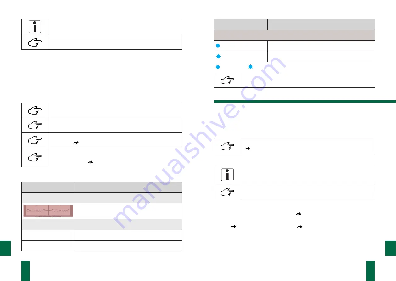
Connection status
Event
Status
Software
Measurement: Measurement view: Measurement value display
No connection
Software
Settings and information
Device connected
Active connection
Device disconnected
No connection
Event
Status
Hand-held device
Active connection
Establishing connection
LED on
LED flashing
The hand-held device always tries to establish a connection to the
user device during operation.
7.3 Measurement
7.3.1 Measurement Preparation
The following steps must be carried out before measuring:
1. Switch on all components of the measuring system.
2. Make sure that the hand-held device and the user device are connected.
The wireless link indicator (3) must be continuously lit.
(
Section 7.2 Connecting the System Components)
3. Connect the sensors to the sensor jacks (6) on the hand-held device.
The measured values are assigned to the jacks:
• left jack („drive“): drive side (DS)
• right jack („operator“): operator side (OS)
The connection cables have different colours in order to easily diffe-
rentiate the measured values to the corresponding sensor osition.
4. Start the software.
5. In the selection menu, select
Measure
(
S
ection 7.4.3 Measure)
.
6. From the overview, select the template associated with the planned measuring
task
(
Template Simple Measurement,
Template Roller Diagram).
7. Confirm the selection by pressing the Start
measuring button
.
Template Simple Measurement
The
Template Simple measurement
is used to measure individual pairs of rollers. It
is generated by the program


