background image

Page 

27

 of 

33


NOTE:

 The process explained in step 13 may have to be repeated after later steps. 


14. Slide the cowling over the engine and temporarily mount your propeller Push the cowling 

over the fuselage`s front edge until gap between the spinner`s back edge and the 

cowling`s front face is 10-15 mm (Figure 16-001 green marking). 


NOTE:

 New engine cowlings are usually too long and need shortening. 


15. Make sure it is cantered left to right along the fuselage´s center line and that the spinner 

backplate rests right between the lower cowl´s two scoops.   


16. Inspect the cowling and spinner from the side. Make sure the spinner´s profile blends into 

the cowling’s profile.  


NOTE:

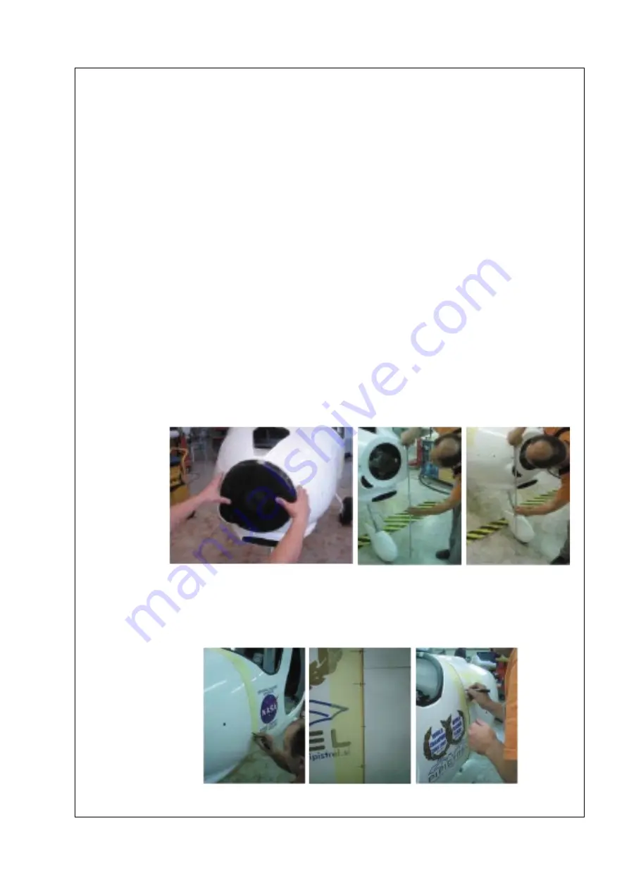
 Other tests to ensure the proper orientation of the cowlings:  


17. Measure the distance between cowling´s halfway seam and the floor on both sides of the 

propeller. Rotate the cowling´s so that the distance is the same. 

18. Check cowling´s halfway seam position regards to the inserts (marked in step 9)) on 

each side of the fuselage. Rotate the fuselage so that there is at least 20 mm distance 

between each insert hole and the cowling´s halfway seam (Figure 16-001 pink marking). 

If 20 mm goal cannot be met, try setting the cowling´s halfway seam in the middle of the 

inserts. 


Figure: 16-004: Cowling’s orientation tests. 


19. When the orientation of the cowling is adequate tape it to the fuselage using masking 

tape. 


Figure: 16-005: Marking the cowling to fuselage orientation. 


Содержание LSA-MRA

Страница 1: ...close to where the MRA was performed as this is something the manufacture cannot check This MRA has been generated based on the aircraft configuration data provided by the owner requester and is to be...

Страница 2: ...thermometer that measures up to 60 deg C Allen key set Angled sander grinder Bit set Heat gun Boxcutter Canister or cart to drain fuel into Chisel Clean smooth and flat table partially covered with P...

Страница 3: ...references 1 POM VARIO 00 65 001 Pipistrel VARIO propeller operators manual latest revision 2 AMM 100 00 60 001 LSA maintenance manual latest revision 3 Sinus 891 SN 912 Firewall repair 4 Sinus 891 S...

Страница 4: ...the baggage compartment See 25 50 in 2 i Remove the fuel lines from under the seat pan See 6 44 40 j Detach any of the lines hoses components attached to the fuselage under the cabin floor and under t...

Страница 5: ...ne which additional parts in the cabin need to be removed for the process to run smoothly Figure 00 002 Example of stretch wrap protection NOTE The picture above is for visual purposes only as the str...

Страница 6: ...n its original form place the template on the firewall and mark all the bolts and holes on the firewall for later re installation See Modification 13 Figure 00 003 Measuring the distance between engin...

Страница 7: ...a smaller amount of microbaloons compound through the hole in the fuselage belly over the support plate on seat pan and on seat backrest as shown in Figure 02 001 part 2 e Prepare some resin and cut...

Страница 8: ...45 45 1x KK300T Pipistrel P N 5073003 45 45 1x 92110 Pipistrel P N 5071002 45 45 Seat backrest laminate plan from inner ply to outer 1x 92110 Pipistrel P N 5071002 45 45 1x Kevlar 200 g m2 twill Pipi...

Страница 9: ...ALLATION NOTE Selection of appropriate drill bits is critical in order to drill the main holes in the undercarriage strut Please refer to the diagram in Figure 04 002 entitled Identification of drill...

Страница 10: ...04 002 Identification of drill geometry and proper undercarriage strut orientation g Run the brake hoses from the undercarriage strut through the holes in the fuselage h Prepare the bottom cover plate...

Страница 11: ...Drill 3 2mm holes on all four corners and in the middle too 6 holes in total Figure 04 004 step 5 m Drill a M4 thread into the 3 2mm holes with tap drill taps bit and fasten the M4 button bolts Figure...

Страница 12: ...ng must lay at 200 220 mm from the ground Figure 05 002 Once the positioning is satisfactory temporarily fix the fairing in place with some adhesive tape e Obtain the fixing hole position as indicated...

Страница 13: ...re 07 002 NOTE Cut made in the seat pan needs to be as accurate as possible for the seat pan insert to fit well Manufacturing a template of the seat pan insert can greatly reduce the margin of error F...

Страница 14: ...irex foam P N 5079026 covered with resin non stick material for example heavy duty brown packaging tape j Secure the foam over the damaged area with firmly applied stretch wrap and with double sided T...

Страница 15: ...Apply 1 50 taper to the fuselage edges and sand until whole repair surface Fuselage edges microbaloons and inner layers is smooth Figure 07 003 step 3 p Blow surface clean with compressed air wipe awa...

Страница 16: ...fine polyester kit and grind sand down using sandpaper no finer than P600 x Paint the newly processed fuselage surfaces with white acrylic paint sand down with P2000 sandpaper and polish with polishin...

Страница 17: ...trel P N 5072006 45 45 1x KK300T Pipistrel P N 5073003 45 45 1x 92110 Pipistrel P N 5071002 45 45 NOTE The first repair ply laid up is always the biggest Each ply that follows should be 7 mm smaller t...

Страница 18: ...INDSHIELD REPLACEMENT and CABIN SUPPORT ASSEMBLY WITH BUSHINGS REPAIR a Assemble the cabin support assembly with bushing levelling tool Figure 09 001 as shown in the Figure 09 002 Figure 09 001 Cabin...

Страница 19: ...the opposite direction by tightening the central bolt NOTE First bring the cabin support assembly with bushing to a levelled position and then apply slightly more force The rod needs to be slightly be...

Страница 20: ...est See 51 10 2 2 in 2 Run a tap test with a smaller metal rod and if any hollow sounds can be heard the fuselage has been damaged Please contact support pipistrel aircraft com for information about h...

Страница 21: ...he seat pan Figure 12 004 e Apply Loctite 406 on the PVC tube to insert joint wait for it to dry and cut the remain of the tube above the insert Figure 12 004 f Place the rudder pedals to its designat...

Страница 22: ...Figure 12 005 k Mark 45 mm aft of the installed insert Figure 12 005 middle figure l Position the pedals to the fwd most position and run the braided cable through the lower PVC tube through spring a...

Страница 23: ...he air intake diffuser See 8 following the process described on pages 6 10 in 10 NOTE Mind that 10 can be used only for illustrative purposes on specified pages since it is published for a different t...

Страница 24: ...ee 6 1 01 27 Make sure to follow the guidelines in 7 x Install the water cooler See 6 1 22 10 and oil thermostat and the oil tank See 6 1 25 26 NOTE Secure electrical wires and fuel hoses to the engin...

Страница 25: ...Once you ve got a nice fit between the upper and lower cowling drill 3 mm holes through both 11 mm above the connecting seam between the upper and lower cowling Drill four holes according to the Figur...

Страница 26: ...t from the center of each insert Figure 16 002 10 Place the cowling on the workbench and mark the 8 cm wide and 20cm long outline for the nosewheel cut out Figure 16 003 Make sure the outline is cente...

Страница 27: ...nner s profile blends into the cowling s profile NOTE Other tests to ensure the proper orientation of the cowlings 17 Measure the distance between cowling s halfway seam and the floor on both sides of...

Страница 28: ...re you repeat step 22 as many times as needed do not rush this step 25 Temporary tape the cowling s to the fuselage with masking tape and repeat the step 9 Extend the lines marked on the fuselage just...

Страница 29: ...and install the holes with the threaded inserts Figure 15 008 New drilled holes and threaded inserts installation 32 Use M4 bolts to fasten the lower cowling to the fuselage and quick connect bolt s t...

Страница 30: ...reinstall it after drilling 37 Reinstall the Akrapovi tailpipe Try reinstalling the lower cowling and while pushing the cowling against the tailpipe gauge the location of the tailpipe opening in the...

Страница 31: ...3 Determine the amount of adhesive foam tape needed to surround the entire oil cooler sides and bottom The tape must cover the whole surface but not overlap the oil cooler more than 1 cm 44 Apply prim...

Страница 32: ...ling just above the oil cooler opening Figure 16 012 Line up the tape s lower edge with the opening s upper edge Apply a bead of black silicone along the outer edge of the tape Smooth it out with a st...

Страница 33: ...r any signs of damage Notify your local Pipistrel dealer of all and any issues BLOCK 10 ENGINEERING DATA not applicable BLOCK 11 OPERATING INSTRUCTIONS to be filled out by the manufacturer Changes to...

Отзывы: