2
8
CDJ-350
1
2
3
4
A
B
C
D
E
F
1
2
3
4
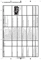
5.3 DIAGNOSIS OF THE PICKUP ASSY
Laser Diode (LD) current
Typ. 65 mA
Max. 75 mA
Focus coil resistance
If the measurement result is beyond the
specified value, the pickup is in failure.
Tracking coil resistance
If the measurement result is beyond the
specified value, the pickup is in failure.
S-shaped level
Usually use a pressed CD, as the
measurement result depends on the disc
type.
Reference: 1.7
V
p-p
If the measurement result is twice or more, or
50 % or less of the reference value, the pickup
or the MAI
N
Assy is defective.
If the measurement result is twice or more, or
50 % or less of the reference value, the pickup
or the MAI
N
Assy is defective.
If the measurement result is twice or more, or
50 % or less of the reference value, the pickup
or the MAI
N
Assy is defective.
Tracking Error (TE) level
Usually use a pressed CD, as the
measurement result depends on the disc
type.
Reference: 1.0
V
p-p
RFO level
Usually use a pressed CD, as the
measurement result depends on the disc
type.
Reference: 1.1
V
p-p
You may disconnect the measuring
equipment during measurement, if you
wish.
You may disconnect the measuring
equipment during measurement, if you
wish.
Auto Gain Control (AGC) RF level
The measurement result does not depend
on the disc type.
If the RFO level value is twice or less, or 50 %
or less of the reference value, and the AGC RF
level is out of the range stipulated in the
specifications, the MAI
N
Assy is defective.
C
N
CT Assy
LD short-circuit
switch
Item
Specifications
Failure Judgment
Remarks
Measurement Procedures
3.7
±
0.55
Ω
4.3
±
0.65
Ω
1.2
V
p-p
±
10 %
1
Make sure that no CD is loaded.
2
Enter Service mode.
3
Connect a tester between the test lands LD3S and
LDCHK
on the MAI
N
Assy
to check the voltage
difference between them.
4
During Test Operation mode, press the TEMPO
button to turn the LD on.
5
Measure the voltage difference (DC value) between the
test lands LD3S and LDCHK on the MAI
N
Assy.
6
Press the TEMPO button to turn the LD off.
Confirm that the voltage difference between test
lands LD3S and LDCHK becomes 0 then
disconnect the tester.
1
Make sure that no CD is loaded.
2
Remove the bottom plate and set the LD short-circuit
switch (S951) to Short side. (see right figure.)
3
Disconnect the FFC cable that connects the C
N
CT
Assy and the MAI
N
Assy from the C
N
201 connector.
4
Measure the conductor resistance of the terminal
assembly between Pins 33 and 34 of the FFC cable.
1
Make sure that no CD is loaded.
2
Remove the bottom plate and set the LD short-circuit
switch (S951) to Short side. (see right figure.)
3
Disconnect the FFC cable that connects the C
N
CT
Assy and the MAI
N
Assy from the C
N
201 connector.
4
Measure the conductor resistance of the terminal
assembly between Pins 31 and 32 of the FFC cable.
1
Enter Service mode.
2
Load a pressed CD. (Standby)
3
Connect and set a digital oscilloscope so that the
p-p level at the test land (FE) can be measured.
4
During Test Operation mode, press the TIME,
then A CUE buttons to send a command.
5
Measure the p-p level (S-shaped level) at the FF.
1
Enter Service mode.
2
Load a pressed CD. (Standby)
3
Connect and set a digital oscilloscope so that the
p-p level at the test land (TE) can be measured.
4
During Test Operation mode, press the buttons in the
following order to send a command: TIME, TEMPO,
RELOOP, then LOOP I
N
twice.
5
Measure the p-p level of waveform at the TE.
1
Play back a pressed CD.
2
Measure the p-p level of RF waveform at the RFO
test land on the MAI
N
Assy.
1
Play back a CD.
2
During playback, measure the p-p level of RF
waveform at the AGCRF test land on the MAI
N
Assy.
The LD can be judged to have degraded if the
LD current, which is calculated by dividing the
measured voltage difference (DC value) by 22,
is 75 mA or higher.
Note:
Check the mounting status of R227, R228,
R232 and R233 (22 ohms).
2
SHORT
OPE
N
Содержание TRAKTOR PRO CDJ-350
Страница 8: ...8 CDJ 350 1 2 3 4 A B C D E F 1 2 3 4 2 2 USABLE DISCS AND USB DEVICES ...
Страница 9: ...9 CDJ 350 5 6 7 8 5 6 7 8 A B C D E F ...
Страница 10: ...10 CDJ 350 1 2 3 4 A B C D E F 1 2 3 4 2 3 PANEL FACILITIES ...
Страница 11: ...11 CDJ 350 5 6 7 8 5 6 7 8 A B C D E F ...
Страница 71: ...71 CDJ 350 5 6 7 8 5 6 7 8 A B C D E F ...
Страница 73: ...73 CDJ 350 5 6 7 8 5 6 7 8 A B C D E F H C 4 4 CN401 ...
Страница 75: ...75 CDJ 350 5 6 7 8 5 6 7 8 A B C D E F H C 4 4 CN401 ...
Страница 79: ...79 CDJ 350 5 6 7 8 5 6 7 8 A B C D E F ...
Страница 91: ...91 CDJ 350 5 6 7 8 5 6 7 8 A B C D E F H H SMPS ASSY SIDE B SIDE B CN1 CN2 FOR SYXJ8 FLXJ KXJ5 and AXJ5 ...
Страница 92: ...92 CDJ 350 1 2 3 4 A B C D E F 1 2 3 4 H H SMPS ASSY SIDE A SIDE A AC POWER CORD CN1 C CN401 CN2 FOR CUXJ ...
Страница 93: ...93 CDJ 350 5 6 7 8 5 6 7 8 A B C D E F H H SMPS ASSY SIDE B SIDE B CN1 CN2 FOR CUXJ ...


