23
CDJ-350
5
6
7
8
5
6
7
8
A
B
C
D
E
F
—
—
—
—
[9] Basic operation
check of CPU/DSP
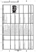
[3-4] Abnormalities regarding the JOG dial
After the JOG Assy is disassembled then reassembled, be sure to check that the load value for the JOG dial is within the
specified range. (Refer to the "8.2 JOG DIAL ROTATIO
N
LOAD ADJUSTME
N
T".)
Turning of the JOG dial is not detected
1
Defective part
P
N
LB Assy
JOGB Assy
Check the waveforms of signal lines.
JOG1_C(IC501-pin 26)
JOG2_C(IC501-pin 25)
If no waveform can be confirmed, the part (PC851)
on the JOGB Assy may be defective.
10.11 WA
V
EFORMS
P
N
LB
5
,
6
2
Defective PA
N
EL
CPU (IC501)
P
N
LB Assy
If the symptom persists after the above
corrections,
Check a mounting state of PA
N
EL CPU (IC501).
If the mounting is OK, the IC501 may be defective.
Pressing on the JOG dial cannot be detected.
1
Defective part
P
N
LB Assy
TCHB Assy
Check the level of TCH_C signal (IC501-pin
27) when the JOG dial is pressed.
If the TCH_C signal (IC501-pin 27) is not set to "L"
when the JOG dial is pressed and it is not set to "H"
when the JOG dial is not pressed, the parts (IC801
and Q801) on the TCHB Assy may be defective.
2
Defective PA
N
EL
CPU (IC501)
P
N
LB Assy
If the symptom persists after the above
corrections,
Check a mounting state of PA
N
EL CPU(IC501).
If the mounting is OK, the IC501 may be defective.
N
oise is heard when the JOG dial is turned.
1
Defective gear
or JOG DIAL B
JOG Assy
There may be any scratches on the gear
or some foreign object between the gears.
If there are any scratches, replace the scratched gear
with a new one. If there is any foreign object, remove
it then replace the gears with new ones. Gears to be
replaced: Load gear, Encoder gear, JOG shaft
There may be any scratches on the JOG
DIAL B or some foreign object.
If sliding surfaces of the sliding sheet are
scratched, replace it with a new one.
If any foreign matter is attached, remove it.
The JOG dial turns too freely. (The load value for the JOG dial is outside the specified range.)
1
Improper adjust-
ment or assembly
of the JOG dial
JOG Assy
Check that the load value for the JOG dial
is within the specified range, referring to
“Measuring method” in “8.2 JOG Dial
Rotation Load Adjustment.”
If it is outside the specified range, adjust the position
of the Cam Plate to change the load value for the
JOG dial, referring to “Load adjustment method” in
“8.2 JOG Dial Rotation Load Adjustment.”
8.2 JOG Dial
Rotation Load
Adjustment.
8.2 JOG Dial
Rotation Load
Adjustment.
During the above adjustment, if the upper-limit adjust-
ment position of the Cam Plate is reached, oil may
have been spattered on the Cam Plate.
Replace the washer, load gear, and cam plate with
new ones, then reassemble.
Resistance to turning the JOG dial is too strong. (The load value for the JOG dial is outside the specified range.)
1
Improper adjust-
ment of the JOG
dial or defective
washer, gear, or
cam plate
JOG Assy
Check that the load value for the JOG dial
is within the specified range, referring to
“Measuring method” in “8.2 JOG Dial
Rotation Load Adjustment.”
If it is outside the specified range, adjust the position
of the Cam Plate to change the load value for the
JOG dial, referring to “Load adjustment method” in
“8.2 JOG Dial Rotation Load Adjustment.”
8.2 JOG Dial
Rotation Load
Adjustment.
8.2 JOG Dial
Rotation Load
Adjustment.
During the above adjustment, if the lower-limit adjust-
ment position of the Cam Plate is reached, shavings
from the worn-out washer may have increased the
friction. Replace the washer, load gear, and cam plate
with new ones, then reassemble.
No.
Cause
Diagnostics Point
Item to be Checked
Corrective Action
Reference
No.
Cause
Diagnostics Point
Item to be Checked
Corrective Action
Reference
No.
Cause
Diagnostics Point
Item to be Checked
Corrective Action
Reference
No.
Cause
Diagnostics Point
Item to be Checked
Corrective Action
Reference
No.
Cause
Diagnostics Point
Item to be Checked
Corrective Action
Reference
Содержание TRAKTOR PRO CDJ-350
Страница 8: ...8 CDJ 350 1 2 3 4 A B C D E F 1 2 3 4 2 2 USABLE DISCS AND USB DEVICES ...
Страница 9: ...9 CDJ 350 5 6 7 8 5 6 7 8 A B C D E F ...
Страница 10: ...10 CDJ 350 1 2 3 4 A B C D E F 1 2 3 4 2 3 PANEL FACILITIES ...
Страница 11: ...11 CDJ 350 5 6 7 8 5 6 7 8 A B C D E F ...
Страница 71: ...71 CDJ 350 5 6 7 8 5 6 7 8 A B C D E F ...
Страница 73: ...73 CDJ 350 5 6 7 8 5 6 7 8 A B C D E F H C 4 4 CN401 ...
Страница 75: ...75 CDJ 350 5 6 7 8 5 6 7 8 A B C D E F H C 4 4 CN401 ...
Страница 79: ...79 CDJ 350 5 6 7 8 5 6 7 8 A B C D E F ...
Страница 91: ...91 CDJ 350 5 6 7 8 5 6 7 8 A B C D E F H H SMPS ASSY SIDE B SIDE B CN1 CN2 FOR SYXJ8 FLXJ KXJ5 and AXJ5 ...
Страница 92: ...92 CDJ 350 1 2 3 4 A B C D E F 1 2 3 4 H H SMPS ASSY SIDE A SIDE A AC POWER CORD CN1 C CN401 CN2 FOR CUXJ ...
Страница 93: ...93 CDJ 350 5 6 7 8 5 6 7 8 A B C D E F H H SMPS ASSY SIDE B SIDE B CN1 CN2 FOR CUXJ ...


