24
CDJ-350
1
2
3
4
A
B
C
D
E
F
1
2
3
4
No.
Cause
Diagnostics Point
Item to be Checked
Corrective Action
Reference
No.
Cause
Diagnostics Point
Item to be Checked
Corrective Action
Reference
No.
Cause
Diagnostics Point
Item to be Checked
Corrective Action
Reference
No.
Cause
Diagnostics Point
Item to be Checked
Corrective Action
Reference
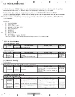
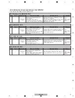
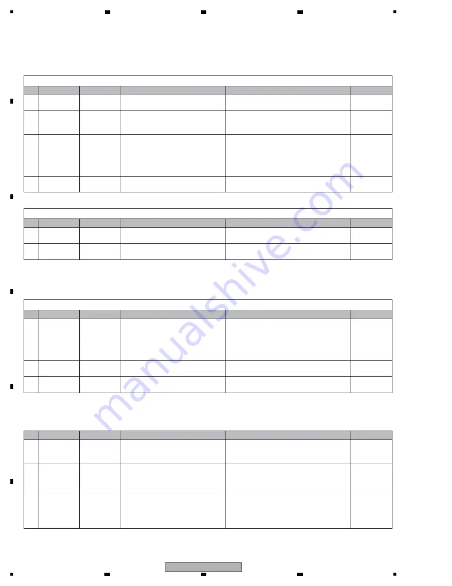
[6] DRIVE ASSY
[6-1] Improper operation of the loading mechanism
1
Improper
soldering
Cables
Check that the wires between the loading
motor and the SLMB Assy are securely
soldered. Check also the wires are not broken.
If soldering is improper, resolder it.
If the wires are broken, replace them.
2
Power failure
MAI
N
Assy
Check the power voltages.
(
V
+7R6M,
V
+5R6M,
V
REF1R65,
V
+3R3B,
V
+3R3,
V
+1R2A)
For any power-supply section that does not output
the voltage, check the mounting statuses of the
regulator IC and its peripheral parts.
If they are properly mounted, then the parts may be
defective.
4.3 POWER SUPPLY
BLOCK DIAGRAM
3
Signal errors
MAI
N
Assy
Check the waveforms of the LPS1 and LPS2
signal lines. (The LPS1 and LPS2 signals
becomes "L" when the SW is set to O
N
.)
If the signal waveform is not proper, the loading
detection SWs (S751/S752) may be improperly
soldered or defective. If soldering is improper,
resolder them. If the symptom persists, replace the
defective parts.
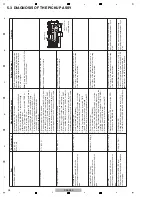
[5] AUDIO OUT
[5-1] No sound
The analog audio signal is not output.
1
Power failure
MAI
N
Assy
Check the voltages for audio (
V
+7R6A,
V
-7R6,
V
+5A,
V
+3R3A).
• If the
V
+7R6A/
V
-7R6 voltage level is abnormal, the
SMPS Assy unit may be defective.
• If the
V
+5A voltage level is abnormal, IC406 may be
defective.
• If the
V
+3R3A voltage level is abnormal, the IC402
may be defective.
2
Loose
connections
MAI
N
Assy
JACK Assy
Check the connection of the audio signal
lines (ROUT/LOUT).
If connection is improper, resolder it.
3
Signal errors
MAI
N
Assy
Check the AUDIO DSP (IC301).
If the AUDIO DSP (IC301) is OK, the DAC (IC302)
may be defective.
—
—
—
—
—
—
—
—
[9] Basic operation
check of CPU/DSP
[9] Basic operation
check of CPU/DSP
[9] Basic operation
check of CPU/DSP
10.10
V
OLTAGES
10.10
V
OLTAGES
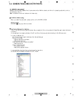
[4] USB (Type A/Type B)
[4-1] No communication via the USB connector (Type A)
Check the following, with a USB device connected to the USB A connector.
1
Loose
connections
P
N
LB Assy
MAI
N
Assy
Check the connection of the USB
communication line.
If connection is improper, resolder it.
2
V
+5USB is
defective.
P
N
LB Assy
Check the voltage level.
If JA505-pin 1 (
V
+5USB) cannot be confirmed and
the IC504-pin 2 can be confirmed, then go to [3].
If
V
+5USB can be confirmed, go to [4].
3
Defective part
P
N
LB Assy
Check the signal level of IC504-5 pin
(USB_CODETFLG) and IC504-4 pin
(USB_
V
BUSO
N
).
• If the IC504-pin 5 (USB_CODETFLG) and IC504-
pin 4 (USB_
V
BUSO
N
) are "H", IC504 may be
defective.
• In the USB device no connection state, If the IC504-
pin 5 (USB_ CODETFLG) is "H" and IC504-pin 4
(USB_
V
BUSO
N
) is "L", IC103 may be defective.
4
Defective MAI
N
CPU
Defective MAI
N
CPU
MAI
N
Assy
If the symptom persists after the above
corrections,
The MAI
N
CPU (IC101) may be defective.
[4-2] No communication via the USB connector (Type B)
Check the following, with a USB device connected to the USB B connector.
1
Loose
connections
Check the connection of the signal lines
(USB_D+/USB_D-).
If connection is improper, resolder it.
2
If the symptom persists after the above
corrections,
The MAI
N
CPU (IC103) may be defective.
Содержание TRAKTOR PRO CDJ-350
Страница 8: ...8 CDJ 350 1 2 3 4 A B C D E F 1 2 3 4 2 2 USABLE DISCS AND USB DEVICES ...
Страница 9: ...9 CDJ 350 5 6 7 8 5 6 7 8 A B C D E F ...
Страница 10: ...10 CDJ 350 1 2 3 4 A B C D E F 1 2 3 4 2 3 PANEL FACILITIES ...
Страница 11: ...11 CDJ 350 5 6 7 8 5 6 7 8 A B C D E F ...
Страница 71: ...71 CDJ 350 5 6 7 8 5 6 7 8 A B C D E F ...
Страница 73: ...73 CDJ 350 5 6 7 8 5 6 7 8 A B C D E F H C 4 4 CN401 ...
Страница 75: ...75 CDJ 350 5 6 7 8 5 6 7 8 A B C D E F H C 4 4 CN401 ...
Страница 79: ...79 CDJ 350 5 6 7 8 5 6 7 8 A B C D E F ...
Страница 91: ...91 CDJ 350 5 6 7 8 5 6 7 8 A B C D E F H H SMPS ASSY SIDE B SIDE B CN1 CN2 FOR SYXJ8 FLXJ KXJ5 and AXJ5 ...
Страница 92: ...92 CDJ 350 1 2 3 4 A B C D E F 1 2 3 4 H H SMPS ASSY SIDE A SIDE A AC POWER CORD CN1 C CN401 CN2 FOR CUXJ ...
Страница 93: ...93 CDJ 350 5 6 7 8 5 6 7 8 A B C D E F H H SMPS ASSY SIDE B SIDE B CN1 CN2 FOR CUXJ ...


