118
C-AX10
1
2
3 4 5
6
7
=
-
0
9
8
7
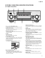
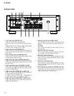
REAR PANEL
1
Front output jacks (FRONT OUT)
These are the front channel output jacks.
In Normal mode, OUT 1 and OUT 2 have the same out-
put.
In Network mode, OUT 1 has high range (HIGH) output
and OUT 2 has low range (LOW) output.
2
Centre output jacks (CENTER OUT)
These are the centre channel output jacks during multi-
channel (six channel) output. Both 1 and 2 have the
same output.
3
Surround output jacks (SURROUND OUT)
These are the surround channel output jacks during
multichannel (six channel) output.
4
Subwoofer output jacks (SUB WOOFER OUT)
These are the subwoofer channel output jacks during
multichannel (six channel) output. Both 1 and 2 have
the same output.
5
Control input/output jacks (CONTROL IN, OUT)
These jacks are used for controlling multiple Pioneer
devices having the
Î
mark from the remote control
sensor of a single device.
6
Digital input jacks (PCM/
2
/DTS DIGITAL IN)
Jacks 1 to 3 are for coaxial cables (COAX) and jacks 4
to 6 are for fiber-optic cables (OPT).
In a PDIF connection, the PDIF jack, 1 COAX jack and
2 COAX jack are used. For details, see page 47.
7
Digital output jacks (PCM/
2
/DTS DIGITAL OUT)
These output jacks are for a coaxial cable (COAX) and
a fiber-optic cable (OPT).
8
Signal ground terminal (SIGNAL GND)
Use this terminal when using an analogue record
player or other device where a signal ground is re-
quired.
CAUTION
This terminal is provided to reduce noise. It is not a
safety ground.
9
ANALOG 3/PHONO input jacks
These jacks are used to select line input or phono in-
put. See page 45 for the selection method.
0
ANALOG 2 input/output jacks
These jacks are used for making analogue connec-
tions to recording or playback devices through the line
input/output jacks.
-
ANALOG 1 input/output jacks
These jacks are used for making analogue connec-
tions to recording or playback devices through the line
input/output jacks.
=
DVD multichannel input jacks (DVD MULTI CH IN)
These jacks are used to connect to a DVD-Audio
player having 6-channel output or a DVD player or
other device having 5.1 channel output.
Содержание C-AX10
Страница 9: ...9 C AX10 ...
Страница 13: ...C AX10 13 A B C D 1 2 3 4 1 2 3 4 E FRAD ASSY F CRAD ASSY 24 576MHz 24 576MHz 3 1 3 A D BLOCK ...
Страница 14: ...C AX10 14 A B C D 1 2 3 4 1 2 3 4 H AUDIO A ASSY 3 1 4 D A BLOCK AUDIO A ASSY ...
Страница 15: ...C AX10 15 A B C D 1 2 3 4 1 2 3 4 I AUDIO B ASSY 3 1 5 D A BLOCK AUDIO B ASSY ...
Страница 16: ...C AX10 16 A B C D 1 2 3 4 1 2 3 4 A DIGITAL I O ASSY B DSP ASSY 3 1 6 DIGITAL SIGNAL BLOCK ...
Страница 17: ...C AX10 17 A B C D 5 6 7 8 5 6 7 8 to D A SECTION Hi bit Hi bit Hi bit ...
Страница 18: ...C AX10 18 A B C D 1 2 3 4 1 2 3 4 A E F Hi bit Hi bit Hi bit FRONT 3 1 7 µ COM PORT BLOCK ...
Страница 19: ...C AX10 19 A B C D 5 6 7 8 5 6 7 8 I AUDIO B ASSY H AUDIO A ASSY K M N L VOLUME ASSY J DISPLAY ASSY G DSP ASSY ...
Страница 35: ...C AX10 35 A B C D 5 6 7 8 5 6 7 8 AUDIO SIGNAL ROUTE 9 3 3V 3 3V x2 1 10W 3 6 G ...
Страница 37: ...C AX10 37 A B C D 5 6 7 8 5 6 7 8 AUDIO SIGNAL ROUTE G1 6 11 11 4 6 G ...
Страница 39: ...C AX10 39 A B C D 5 6 7 8 5 6 7 8 G1 6 5 6 G ...
Страница 45: ...C AX10 45 A B C D 5 6 7 8 5 6 7 8 PCB BINDER VEF1040 The power supply is shown with the marked box I ...
Страница 56: ...C AX10 56 A B C D 1 2 3 4 1 2 3 4 SG ASSY D FRAD ASSY E Q406 Q405 Q408 Q419 Q420 Q404 Q403 Q409 Q421 Q422 D E ...
Страница 59: ...C AX10 59 A B C D 1 2 3 4 1 2 3 4 CRAD ASSY F ANP7292 B IC2804 IC2704 Q2801 Q2802 Q2702 Q2701 SIDE B F ...
Страница 66: ...C AX10 66 A B C D 1 2 3 4 1 2 3 4 AUDIO A ASSY H SIDE B Q910 Q912 Q908 Q902 Q901 Q907 Q903 H ...
Страница 67: ...C AX10 67 A B C D 5 6 7 8 5 6 7 8 Q901 Q905 Q906 Q904 907 Q903 ANP7291 D H ...
Страница 70: ...C AX10 70 A B C D 1 2 3 4 1 2 3 4 AUDIO B ASSY I SIDE B Q1013 Q1003 Q1007 Q1002 Q100 Q1008 Q1015 Q1011 I ...
Страница 71: ...C AX10 71 A B C D 5 6 7 8 5 6 7 8 Q1003 Q1007 Q1001 Q1005 Q1006 Q1004 Q1009 ANP7291 D I ...

