114
C-AX10
DOLBY
D I G I T A L
0 - =
~ !@ # $
% ^ & * ( ) _ + ¡™
%
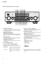
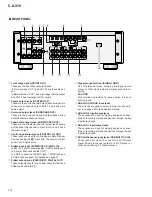
CHARACTER INPUT button
✽
This button is used to enter the Character Input mode
for changing the input signal or sound memory setting
to a user-selected name.
^
Digital REC Selector button
(REC SELECTOR [DIGITAL] )
✽
This button is used to enter the mode for selecting the
REC OUT signal that is output from the digital output
jack.
&
INPUT GAIN button
✽
This button is used to enter the mode for adjusting the
analogue input and digital input gain.
*
PARAMETER CHECK button
✽
This button is used to enter the mode for checking the
current settings.
(
Tone Control button (TONE)
✽
This button is used to enter Tone Control mode.
)
Tone Control Channel button (EACH/ALL)
✽
This button is used to switch between EACH mode and
ALL mode.
÷
EACH mode
: The front, centre, and surround
channels can each be set individu-
ally.
÷
ALL mode
: The front, centre, and surround
channels are set to the same set-
tings.
_
Balance Control button (BALANCE)
✽
This button is used to enter the mode for adjusting the
balance of the front left and right channels.
+
SYSTEM SET UP button
✽
This button is used to enter System Setup mode for
speaker setup or selecting modes.
¡
NETWORK SET UP button
✽
This button is used to enter Network Setup mode when
the OUTPUT MODE selector (
™
) is set to Digital Net-
work FIR mode or Digital Network IIR mode.
™
OUTPUT MODE selector
This selector is used to set to one of the following four
modes.
÷
Digital Network FIR mode
÷
Digital Network IIR mode
÷
Normal mode
÷
OFF (Output off)
✽
After pressing the buttons in
%
to
¡
, use the MULTI
CONTROL jog dial
8
to make the settings and adjust-
ments.
When the front flip-down door is opened
Содержание C-AX10
Страница 9: ...9 C AX10 ...
Страница 13: ...C AX10 13 A B C D 1 2 3 4 1 2 3 4 E FRAD ASSY F CRAD ASSY 24 576MHz 24 576MHz 3 1 3 A D BLOCK ...
Страница 14: ...C AX10 14 A B C D 1 2 3 4 1 2 3 4 H AUDIO A ASSY 3 1 4 D A BLOCK AUDIO A ASSY ...
Страница 15: ...C AX10 15 A B C D 1 2 3 4 1 2 3 4 I AUDIO B ASSY 3 1 5 D A BLOCK AUDIO B ASSY ...
Страница 16: ...C AX10 16 A B C D 1 2 3 4 1 2 3 4 A DIGITAL I O ASSY B DSP ASSY 3 1 6 DIGITAL SIGNAL BLOCK ...
Страница 17: ...C AX10 17 A B C D 5 6 7 8 5 6 7 8 to D A SECTION Hi bit Hi bit Hi bit ...
Страница 18: ...C AX10 18 A B C D 1 2 3 4 1 2 3 4 A E F Hi bit Hi bit Hi bit FRONT 3 1 7 µ COM PORT BLOCK ...
Страница 19: ...C AX10 19 A B C D 5 6 7 8 5 6 7 8 I AUDIO B ASSY H AUDIO A ASSY K M N L VOLUME ASSY J DISPLAY ASSY G DSP ASSY ...
Страница 35: ...C AX10 35 A B C D 5 6 7 8 5 6 7 8 AUDIO SIGNAL ROUTE 9 3 3V 3 3V x2 1 10W 3 6 G ...
Страница 37: ...C AX10 37 A B C D 5 6 7 8 5 6 7 8 AUDIO SIGNAL ROUTE G1 6 11 11 4 6 G ...
Страница 39: ...C AX10 39 A B C D 5 6 7 8 5 6 7 8 G1 6 5 6 G ...
Страница 45: ...C AX10 45 A B C D 5 6 7 8 5 6 7 8 PCB BINDER VEF1040 The power supply is shown with the marked box I ...
Страница 56: ...C AX10 56 A B C D 1 2 3 4 1 2 3 4 SG ASSY D FRAD ASSY E Q406 Q405 Q408 Q419 Q420 Q404 Q403 Q409 Q421 Q422 D E ...
Страница 59: ...C AX10 59 A B C D 1 2 3 4 1 2 3 4 CRAD ASSY F ANP7292 B IC2804 IC2704 Q2801 Q2802 Q2702 Q2701 SIDE B F ...
Страница 66: ...C AX10 66 A B C D 1 2 3 4 1 2 3 4 AUDIO A ASSY H SIDE B Q910 Q912 Q908 Q902 Q901 Q907 Q903 H ...
Страница 67: ...C AX10 67 A B C D 5 6 7 8 5 6 7 8 Q901 Q905 Q906 Q904 907 Q903 ANP7291 D H ...
Страница 70: ...C AX10 70 A B C D 1 2 3 4 1 2 3 4 AUDIO B ASSY I SIDE B Q1013 Q1003 Q1007 Q1002 Q100 Q1008 Q1015 Q1011 I ...
Страница 71: ...C AX10 71 A B C D 5 6 7 8 5 6 7 8 Q1003 Q1007 Q1001 Q1005 Q1006 Q1004 Q1009 ANP7291 D I ...


