- 7 -
Betrieb
Beim Einschalten der Versorgungsspannung
übernimmt das Sicherheits-
system PNOZmulti die Konfiguration aus der
Chipkarte. Alle LEDs leuchten während des
Einschalttests. Das Gerät ist betriebsbereit,
wenn die LED "READY" dauerhaft leuchtet.
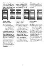
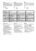
LED-Anzeige
LED aus
LED leuchtet
LED blinkt
LED-Zustand
LED status
LED
のステータス
grün/green/
緑
rot/red/
赤
rot/red/
赤
gelb/yellow/
黄色
Bedeutung
das PNOZ mlp ist betriebsbereit
das PNOZ mlp ist nicht
betriebsbereit
Externer Fehler: z. B
Verdrahtungsfehler
Interner Fehler
kein Fehler
Verbindung zu anderem
PNOZ mlp vorhanden
keine Verbindung zu anderem
PNOZ mlp
LED
READY
FAULT
TR
Meaning
The PNOZ mlp is ready for operation
The PNOZ mlp is not ready for
operation
External error:
e.g. wiring error
Internal error
No error
Connection to
other PNOZ mlp available
No connection to other PNOZ mlp
動作
供給電圧が
ON
になると、
PNOZmulti
安全コン
トローラはチップカードからコンフィグレーショ
ンをコピーします。起動テスト中は、すべての
LED
が点灯します。ユニットが動作可能な状態
になると、「
READY
」の
LED
がそのまま点灯を
続けます。
LED
LED
消灯
LED
点灯
LED
点滅
Fehlererkennung:
Jedes der Basisgeräte erhält Informationen
über
• das eigene Verbindungsmodul
(in Ordnung, defekt, keine
Versorgungungsspannung)
• den Status der Verbindung (ja, nein)
• den Betriebszustand des verbundenen
Basisgeräts (RUN, STOP)
Wenn die Verbindung unterbrochen ist,
dann schalten die Basisgeräte die virtuellen
Eingänge auf Null. Die Basisgeräte
verbleiben im RUN.
Defekt des Verbindungsmoduls:
• Das zugehörige Basisgerät geht in
STOP. Die virtuellen Ausgänge des
Verbindungsmoduls werden auf Null
gesetzt.
• Das verbundene Basisgerät verbleibt im
RUN.
Fault detection:
Each of the base units receives information
about
• its own connection module (in order,
defective, no supply voltage)
• the status of the connection (yes, no)
• the operating status of the connected base
unit (RUN, STOP)
When the connection is interrupted, the base
units switch the virtual inputs to zero. The
base units remain in RUN.
Defective connection module:
• The corresponding base unit goes
into STOP. The virtual outputs on the
connection module are set to zero.
• The connected base unit remains in RUN.
故障の検出
:
各ベースユニットは、以下の情報を受信します。
•
自己のセーフティリンクモジュールのステー
タス
(
正常、故障、供給電圧無し
)
•
接続のステータス
(
接続、未接続
)
•
接続されているベースユニットのオペレー
ティングステータス
(RUN
、
STOP)
接続が中断されると、ベースユニットでは仮想入
力がゼロに切り替わります。ベースユニットのス
テータスは
RUN
のまま変化しません。
セーフティリンクモジュールが故障している場合
:
•
対応するベースユニットのステータスが
STOP
と表示されます。セーフティリンクモジュール
の仮想出力はゼロにセットされます。
•
接続されているベースユニットのステータス
は
RUN
のまま変化しません。
意味
PNOZ mlp
は動作可能な状態
PNOZ mlp
は動作可能な状態ではない
外部エラー
:
配線エラーなど
内部エラー
エラー無し
他の
PNOZ mlp
への
接続が可能
他の
PNOZ mlp
に接続不可
Operation
When the supply voltage is switched on,
the PNOZmulti safety system copies the
configuration from the chip card. All LEDs
illuminate during the power-up test. The unit
is ready for operation when the "READY"
LED is continuously illuminated.
LEDs
LED off
LED on
LED flashes
Содержание PNOZ ml1p
Страница 9: ...Notizen Notes...
Страница 11: ...11...

