- 0 -
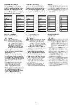
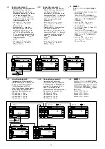
Anschlussbeispiel 1:
Reihenschaltung von 3 Basisgeräten
• Reaktionszeit t
SUM
zwischen
Basisgerät Base und Base 2:
Eingangsverzögerung t
ON
an I3 und
I6 + Datenübertragungszeit
* t
BUS
durch Verbindungsmodul
+ Ausschaltverzögerung t
COND
des
Halbleiterausgangs an O0
• t
SUM
= t
ON
+ (n * t
BUS
) + t
COND
t
SUM
= 4 ms + ( * 35 ms ) +
30 ms = 69 ms
• Reaktionszeit t
SUM
zwischen
Basisgerät Base und Base 3:
Eingangsverzögerung t
ON
an I3
und I6 + Datenübertragungszeit
2 * t
BUS
durch Verbindungsmodule
+ Ausschaltverzögerung t
COND
des
Halbleiterausgangs
an O
• t
SUM
= t
ON
+ (n * t
BUS
) + t
COND
t
SUM
= 4 ms + (2 * 35 ms ) +
30 ms = 04 ms
Connection example 1:
Series connection of 3 base units
• Reaction time t
SUM
between base
unit Base and Base 2:
Input delay t
ON
at I3 and I6 + data
transmission time * t
BUS
through
connection switch-off
delay t
COND
of semiconductor
output at O0
• t
SUM
= t
ON
+ (n * t
BUS
) + t
COND
t
SUM
= 4 ms + ( * 35 ms ) +
30 ms = 69 ms
• Reaction time t
SUM
between base
unit Base and Base 3:
Input delay t
ON
at I3 and I6 + data
transmission time 2 * t
BUS
through
connection switch-off
delay t
COND
of semiconductor
output
at O
• t
SUM
= t
ON
+ (n * t
BUS
) + t
COND
t
SUM
= 4 ms + (2 * 35 ms ) +
30 ms = 04 ms
4
GB
4
D
4
日
���������
�����
�
���������
���������
�����
�
�����
�
�����
�
�����
�
���������
�����
�
���������
�����
�
�����
�
������
������
������
������
������
��
�� ��
��
��
��
��
��
��
��
��
Anschlussbeispiel 2:
Verbindung von 5 Basisgeräten
Die Reaktionszeiten errechnen sich
analog zu Anwendungsbeispiel
. Nach Betätigen von S an
Base schalten die Ausgänge der
verbundenen Basisgeräte nach
folgenden Reaktionszeiten t
SUM
:
O0 von Base 2: 69 ms
O von Base 3: 04 ms
O0 von Base 4: 39 ms
O0 von Base 5: 04 ms
Connection example 2:
Connection of 5 base units
The reaction times are calculated
in the same way as to application
example . After pressing S on
Base , the outputs on the
connected base units operate after
the following reaction time t
SUM
:
O0 of Base 2: 69 ms
O of Base 3: 04 ms
O0 of Base 4: 39 ms
O0 of Base 5: 04 ms
4
GB
4
D
4
日
���������
�����
�
���������
���������
�����
�
�����
�
�����
�
��
��
��
�� ��
��
��
������
������
������
接続例
1:
3
台のベースユニットを直列に接続する
場合
•
ベースユニット
Base
と
Base 2
の
間の応答時間
t
SUM
:
I3
および
I6
での入力応答時間
t
ON
+
セーフティリンクモジュールでの通信
時間
* t
BUS
+ O0
での半導体出力の
応答時間
t
COND
• t
SUM
= t
ON
+ (n * t
BUS
) + t
COND
t
SUM
= 4 ms + ( * 35 ms ) +
30 ms = 69 ms
•
ベースユニット
Base
と
Base 3
の
間の応答時間
t
SUM
:
I3
および
I6
での入力応答時間
t
ON
+
セーフティリンクモジュールでの通信
時間
2 * t
BUS
+ O
での半導体出力の
応答時間
t
COND
• t
SUM
= t
ON
+ (n * t
BUS
) + t
COND
t
SUM
= 4 ms + (2 * 35 ms ) +
30 ms = 04 ms
接続例
2:
5
台のベースユニットを接続する場合
応答時間は、アプリケーション例
と同
じ方法で算出します。
Base
の
S
を
ON
にすると、接続されたベースユニッ
トの出力が以下の応答時間
t
SUM
経過後に
動作します。
Base 2
の
O0: 69 ms
Base 3
の
O: 04 ms
Base 4
の
O0: 39 ms
Base 5
の
O0: 04 ms
Содержание PNOZ ml1p
Страница 9: ...Notizen Notes...
Страница 11: ...11...

