- 4 -
PNOZ ml1p montieren
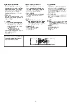
Beachten Sie bei der Montage:
Achtung!
Durch elektrostatische
Entladung können Bauteile der
Sicherheitssteuerung beschädigt
werden. Sorgen Sie für Entladung,
bevor Sie die Sicherheitssteuerung
berühren, z. B. durch Berühren
einer geerdeten, leitfähigen Fläche
oder durch Tragen eines geerdeten
Armbands.
• Montieren Sie das Sicherheitssystem in
einen Schaltschrank mit einer Schutzart
von mindestens IP54.
• Montieren Sie das Sicherheitssystem
auf eine waagrechte Tragschiene. Die
Lüftungsschlitze müssen nach oben und
unten zeigen (siehe Betriebsanleitung des
Basisgeräts). Andere Einbaulagen können
zur Zerstörung des Sicherheitssystems
führen.
• Befestigen Sie das Sicherheitssystem
mit Hilfe der Rastelemente auf der
Rückseite auf einer Normschiene.
Führen Sie das Sicherheitssystem
gerade auf die Normschiene, so dass die
Erdungsfedern am Sicherheitssystem auf
die Normschiene gedrückt werden.
• Um die EMV-Anforderungen einzuhalten,
muss die Normschiene mit dem
Schaltschrankgehäuse niederohmig
verbunden sein.
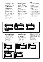
Basisgerät
Virtuelle
Ausgänge
o0
...
o3
Virtuelle
Eingänge
i0
...
i3
Basisgerät 2
Virtuelle
Eingänge
i0
...
i3
Virtuelle
Ausgänge
o0
...
o3
➩
➩
➩
➩
➩
➩
PNOZ ml1p
の取り付け
取り付け時の注意
:
注意
!
静電放電により、安全コントローラの部
品が損傷するおそれがあります。安全コ
ントローラに触れる前に、接地されてい
る導電性のある表面に触れるか、または
接地されているアームバンドを着用する
などの方法で、放電対策を講じてくだ
さい。
•
安全コントローラは、保護構造が少なくとも
IP54
の制御盤に取り付ける必要があります。
•
安全コントローラは、水平な
DIN
レールに合
わせて取り付けます。また、通気口が上下の
向きになるようにしてください
(
ベースユニッ
トの取扱説明書を参照してください
)
。これ以
外の位置に取り付けた場合、安全コントロー
ラが破損するおそれがあります。
•
安全コントローラの背面にある刻み目を使用
して、
DIN
レールに取り付けます。安全コン
トローラを直立させた状態で
DIN
レールに
載せ、安全コントローラの接地スプリングを
DIN
レールに押し付けるようにして接続します。
• EMC
要件に適合させるため、
DIN
レールは低
インピーダンスの状態で制御盤のハウジング
に接続する必要があります。
Installing the PNOZ ml1p
Please note for installation:
Caution!
Electrostatic discharge can damage
components on the safety system.
Ensure against discharge before
touching the PSS, e.g. by touching
an earthed, conductive surface or by
wearing an earthed armband.
• The safety system should be installed in a
control cabinet with a protection type of at
least IP54.
• Fit the safety system to a horizontal
DIN rail. The venting slots must point up
and down (see operating instructions for
the base unit). Other mounting positions
could destroy the safety system.
• Use the notches on the rear of the safety
system to attach it to a DIN rail. Connect
the safety system to the DIN rail in an
upright position so that the earthing
springs on the safety system are pressed
on to the DIN rail.
• To comply with EMC requirements, the
DIN rail must have a low impedance
connection to the control cabinet housing.
Base unit
Virtual
outputs
o0
...
o3
Virtual
inputs
i0
...
i3
Base unit 2
Virtual
inputs
i0
...
i3
Virtual
outputs
o0
...
o3
➩
➩
➩
➩
➩
➩
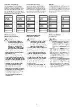
Virtuelle Ein- und Ausgänge:
Die Zuordnung der Ein- und Ausgänge
der beiden PNOZmulti-Systeme wird im
PNOZmulti Configurator festgelegt. Die Ein-
und Ausgänge mit gleicher Nummer sind
einander zugeordnet, z. B der Ausgang o5
des einen PNOZmulti-Systems dem Eingang
i5 des anderen PNOZmulti-Systems.
Virtual inputs and outputs:
Inputs and outputs for both PNOZmulti
systems are assigned in the PNOZmulti
Configurator. Inputs and outputs with the
same number are assigned to each other,
e.g. output o5 on one PNOZmulti system to
input i5 on the other PNOZmulti system.
仮想入出力
:
入力側、出力側の両方とも、
PNOZmulti
システ
ムの入出力の割り付けは
PNOZmulti
コンフィグ
レータで行います。同じ番号の入出力を互いに組
み合わせる形で割り付けます。たとえば、出力
o5
は、もう一方の
PNOZmulti
システムの入力
i5
に割り付けます。
ベースユニット
仮想
出力
o0
...
o3
仮想
入力
i0
...
i3
ベースユニット
2
仮想
入力
i0
...
i3
仮想
出力
o0
...
o3
➩
➩
➩
➩
➩
➩
Содержание PNOZ ml1p
Страница 9: ...Notizen Notes...
Страница 11: ...11...

