background image

PZE X5

Operating Manual PZE X5
1003301­EN­05

13

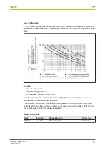
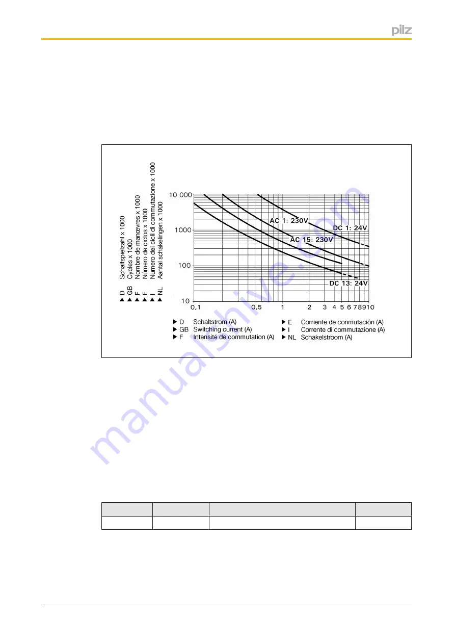
Service life graph

The service life graphs indicate the number of cycles from which failures due to wear must
be expected. The wear is mainly caused by the electrical load; the mechanical load is negli­
gible.

Example

}

Inductive load: 0,2 A

}

Utilisation category: AC15

}

Contact service life: 4,000,000 cycles

Provided the application requires fewer than 4,000,000 cycles, the PFH value (see tech­
nical details) can be used in the calculation.

To increase the service life, sufficient spark suppression must be provided on all output
contacts. With capacitive loads, any power surges that occur must be noted. With contact­
ors, use freewheel diodes for spark suppression.

Order reference

Type

Features

Connection type

Order no.

PZE X5

24 V DC

Screw terminals

774595

Содержание 774595
Страница 1: ...PZE X5 Operating Manual 1003301 EN 05 Safety relays...

Страница 2: ...KG Copies may be made for internal purposes Suggestions and comments for improving this documentation will be gratefully received Pilz PIT PMI PNOZ Primo PSEN PSS PVIS SafetyBUS p SafetyEYE SafetyNET...

Страница 3: ...fety 5 Unit features 5 Safety features 5 Block diagram terminal configuration 6 Function description 6 Installation 7 Wiring 7 Preparing for operation 8 Operation 8 Status indicators 8 Faults Interfer...

Страница 4: ...This warning must be heeded It warns of a hazardous situation that poses an immediate threat of serious injury and death and indicates preventive measures that can be taken WARNING This warning must b...

Страница 5: ...regulations are met especially those relating to safety Any guarantee is rendered invalid if the housing is opened or unauthorised modifica tions are carried out Note for overvoltage category III If v...

Страница 6: ...ice without delay on de energisation and it is used to expand a safety circuit The contact expansion module is driven by a base unit e g emergency stop relay Functional procedure when the supply volta...

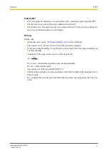
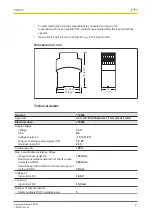
Страница 7: ...cal details 9 must be followed The outputs 13 14 23 24 33 34 43 44 53 54 are safety contacts To prevent contact welding a fuse should be connected before the output contacts see Technical details Calc...

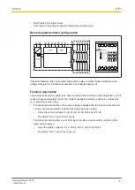
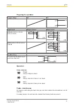
Страница 8: ...ss contacts K1 K2 U Y4 Y3 PZE U Feedback loop Y1 and Y2 are feedback loop in puts on the base unit Operation Status indicators Power Supply voltage is present CH 1 Safety contacts of channel 1 are clo...

Страница 9: ...95 Approvals CCC CE EAC Eurasian T V cULus Listed Electrical data 774595 Supply voltage Voltage 24 V Kind DC Voltage tolerance 15 10 Output of external power supply DC 3 5 W Residual ripple DC 20 Cont...

Страница 10: ...lisation category in accordance with UL Voltage 240 V AC G P With current 8 0 A Voltage 24 V DC G P Resistive With current 5 0 A Pilot Duty B300 C600 R300 Contact fuse protection external safety conta...

Страница 11: ...95 Climatic suitability EN 60068 2 78 Ambient temperature Temperature range 10 55 C Storage temperature Temperature range 40 85 C Condensation during operation Not permitted EMC EN 60947 5 1 EN 61000...

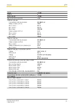
Страница 12: ...D EN ISO 13849 1 2008 TM year PL e Cat 4 SIL CL 3 2 31E 09 SIL 3 2 03E 06 20 All the units used within a safety function must be considered when calculating the safety characteristic data INFORMATION...

Страница 13: ...ategory AC15 Contact service life 4 000 000 cycles Provided the application requires fewer than 4 000 000 cycles the PFH value see tech nical details can be used in the calculation To increase the ser...

Страница 14: ...et the requirements of the directive 2006 42 EC for ma chinery of the European Parliament and of the Council The complete EC Declaration of Conformity is available on the Internet at www pilz com supp...

Страница 15: ...mo PMCprotego PMCtendo PMD PMI PNOZ Primo PSEN PSS PVIS SafetyBUS p SafetyEYE SafetyNET p the spirit of safety are registered and protected trademarks of Pilz GmbH Co KG in some countries We would poi...

Отзывы: