3
www.phywe.com, © All rights reserved
12620-09 and 12620-10 / 2715
3.3
USB interface for the PC
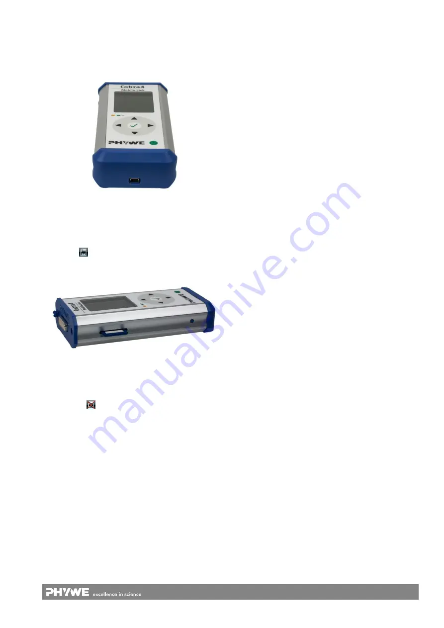
A USB mini-socket is integrated into the sealing cap at the
front of the device (Fig. 4). It is used for the data transfer to
the PC (after the measurement or simultaneously) and for
charging the integrated battery.
3.3
Recording function of the memory card
The recording of measurement values requires a memory
card (e.g. part no. 12620-01; SD/MMC format). Push the card
into the slot in the housing until it locks into place. On the
display, the
symbol will be displayed in the header.
In order to unlock the card, press against it and remove it
(Fig. 5).
If no memory has been inserted, a warning sound will be
issued and a warning symbol will be displayed in the header
of the display:
.
4
NOTES ON OPERATION
The device fulfils the technical requirements that are summa-
rised in the current directives of the European Community.
The product characteristics entitle the unit to bear the CE
mark. Compliance with the following instructions must be
ensured:
-
The unit must be used under the supervision of an ex-
pert and in an electromagnetically controlled environ-
ment at research, teaching, and training facilities
(schools, universities, institutes, and laboratories).
This means that, in such an environment, radio trans-
mission devices, e.g. mobile phones, should not be used
in the direct vicinity of the unit. The connected cables
must not be longer than 2
m.
-
The measurement data recording process as well as the
general operation of the device can be influenced by ra-
diofrequency fields.
-
Electrostatic charges or similar electromagnetic phe-
nomena (HF, bursts, indirect lightning discharge, etc.)
may affect the unit so that it will not work within the
specified data range.
The following measures reduce or eliminate the poten-
tial interferences: Ensure equipotential bonding and use
shielding when using the device in combination with a
PC (in particular with a laptop computer). Do not use
radiofrequency transmitters (e.g. radio sets or mobile
phones) in the direct vicinity of the unit. After a complete
shut-down of the unit, it must be switched off and on
again by way of the ON/OFF switch (operating ele-
ment
①
). If the unit does not react, keep the ON/OFF
switch pressed for more than 3 seconds so that the unit
will restart.
5
MOBILE HANDLING
This section describes the start-up of the Cobra4 Mobile-
Link 2 and provides an overview of its handling. Please read
this section thoroughly in order to avoid failures or operating
errors.
5.1
Start-up
If the unit is used for the first time, charge the integrated
battery via the USB interface. This can be realised either with
the supplied power supply unit or with the aid of the USB
cable that must be connected to a computer. The charging
process is indicated by the battery LED on the front of the
unit and, if the unit is switched on, in the header of the dis-
play.
In order to record measurement data, the memory card must
be inserted beforehand as described under 3.3.
If the stored data are to be displayed and evaluated on the
PC by way of the measurement evaluation software "meas-
ure", the necessary drivers and programs must be installed
on the PC beforehand via the supplied CD. To do so, insert
the supplied "measure" CD into the drive of your PC and
follow the instructions.
5.2
Starting the unit
The unit is switched on by way of the ON/OFF switch as
described in 3.1.1.
After the unit has been switched on, the start screen will be
displayed. The header of the display includes various sym-
bols that describe the status of the unit.
If no Cobra4 Sensor-Unit is connected to the device, the
Cobra4 Mobile-Link 2 automatically uses the three measuring
channels of the integrated acceleration sensor. This is con-
firmed in the header of the display by way of the word "Ac-
celeration".
In the upper half of the display, i.e. in the main field, one of
the three channels of the acceleration sensor and the associ-
ated measured values are displayed in a large form. The
other two measuring channels are displayed in smaller form
in the field below.
The footer of the display shows the existing navigation op-
tions of the user (see Fig. 6).
Fig. 4: Cobra4 Mobile-Link 2
– front with USB interface
Fig. 5: Cobra4 Mobile-Link 2
– view from the side with the
slot for the memory card.


