


Product description
106888_en_01
PHOENIX CONTACT
21
2.8
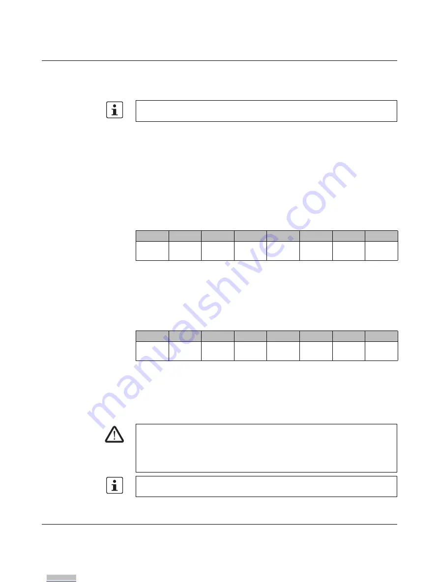
Process data words
The module occupies four words in the Axioline F system.
The module has feedback data and enable data.
Feedback data
The bits in this register mirror the states of the digital outputs as diagnostic data. This data
can be used if an output has been parameterized with a switch-off delay. In this case, the
feedback data can be used to determine the actual state of the output and derive
information for the standard control process from this.
•
Please note that the feedback data for certain errors (e.g., communication error) can
differ from the actual state of the outputs.
•
Do not use the diagnostic data to execute safety-related functions or actions.
The structure and function of the register are as follows:
Enable
The enable principle is implemented in the SafetyBridge system. For this, all modules with
local outputs have an enable function integrated in the device firmware (ANDed bit-by-bit)
for each local safe output channel. The enable function can be parameterized
(enabled/disabled) for each output pair.
The structure and function of the register are as follows:
When the enable function is enabled, the relevant safe local output is ANDed bit-by-bit with
the corresponding output bit of the standard controller. This output is then only set if the
result of the safety function calculation permits this and the standard controller has set the
corresponding output.
The enable function is performed according to the single-channel or two-channel
parameterization of the safe outputs.
Access the process data words via the “Operate” function block.
Table 2-2
Feedback data register (mirrored data)
7
6
5
4
3
2
1
0
OUT3
_Ch2
OUT3
_Ch1
OUT2
_Ch2
OUT2
_Ch1
OUT1
_Ch2
OUT1
_Ch1
OUT0
_Ch2
OUT0
_Ch1
Table 2-3
Enable data register
7
6
5
4
3
2
1
0
OUT3
_Ch2
OUT3
_Ch1
OUT2
_Ch2
OUT2
_Ch1
OUT1
_Ch2
OUT1
_Ch1
OUT0
_Ch2
OUT0
_Ch1
WARNING: Loss of safety function
The safety function must be triggered and canceled via the SafetyBridge system. If the
safety function is triggered and canceled via standard components, there is no safety
function.
•
Check this when validating the overall safety function.
The enable function is not graphically represented in SAFECONF in the safety logic editor.
Parameterize the enable function when parameterizing the channels.
Downloaded from
Downloaded from
Downloaded from
Downloaded from
Downloaded from
Downloaded from
Downloaded from
Downloaded from
Downloaded from
Downloaded from
Downloaded from
Downloaded from
Downloaded from
Downloaded from
Downloaded from
Downloaded from
Downloaded from
Downloaded from
Downloaded from
Downloaded from
Downloaded from