1-9
INSTALLATION
Installation
Step 3:
Connecting
TV
IMPOR
T
ANT!
–Y
ou onl
y need to mak
e one video
connection fr
om the follo
wing options,
depending on the ca
pabilities of y
our
TV
.
–
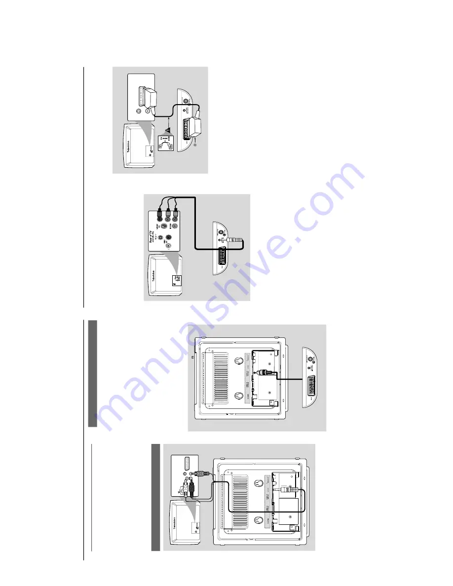
Connect the D
VD system dir
ectl
y to
the TV
.
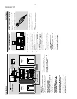
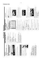
Using A
V
OUT
jack
AUD
IO
IN
S-VIDEO
IN
VIDEO IN
TV IN
AUDIO
IN
S-VIDEO
IN
VIDEO IN
TV IN
1
Connect the end of the supplied
AV
cord with
onl
y one connector to the
AV
OUT
jack of the
D
VD system.
2
For the other end, connect the video output
connector (y
ello
w) to the video input jack (or
labeled as
A/
V In,
CVBS,
Composite or
Baseband) on the
TV
. T
o hear the sound of this
D
VD system through y
our
TV
, connect the audio
connector
s (white/ red) to the audio input jacks
on the
TV
.
Using the video bo
x
IMPOR
T
ANT!
–A
SCAR
T connection will let y
ou use
features both
Audio and
Video on the
D
VD Pla
y
er
.
The supplied video bo
x pro
vides y
ou with more
TV connection options.
Fir
st connect the 9-pin connector of the
supplied video bo
x to the
CONNECT T
O
VIDEO BO
X
jack on the back of the set b
y
matching the pins.
Installation
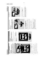
Using Component
Video jacks (Y Pb
Pr)
IMPOR
T
ANT!
–
The pr
o
gressiv
e scan video quality is
onl
y possib
le when using
Y Pb Pr
, and a
pr
o
gressiv
e scan
TV is r
equir
ed.
R
1
Use component video cab
les (red/b
lue/green) to
connect the
COMPOENT VIDEO
OUTPUT
(
Pr/Cr Pb/Cb
Y
) jack to the
corresponding Component video input jacks (or
labeled as
Y Pb/Cb Pr/Cr or
YUV) on the
TV
.
2
If y
ou are using a Progressiv
e Scan
TV (TV must
indicate Progressiv
e Scan or ProScan capability),
to activate
TV Progressiv
e Scan,
please refer to
your
TV user man
ual.
For D
VD system
Progressiv
e Scan function,
see "Preparations-
Setting up Progressiv
e Scan f
eature".
Note:
–
If your
TV does not suppor
t Pr
ogr
essive Scan,
you
will not be able to vie
w the pictur
e
.
Pr
ess SYSTEM MENU on the r
emote to exit the
system menu and then DISC to exit pr
ogr
essive
scan.
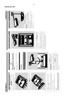
Use the
SC
AR
T
cable (b
lack) to connect the
D
VD Pla
yer’
s SC
AR
T jack (
SCAR
T
) to
the
cor
responding Scar
t input jacks on the
TV
.
Note:
–
Ensur
e that the
“TV”
indication on SC
AR
T cable
is connected to the
TV set and
“D
VD”
indication on
SC
AR
T cable is connected to the D
VD Play
er
.
Using SCAR
T jack
AUDIO
IN
S-VID
EO
IN
VIDEO IN
TV IN
S-VIDEO
IN
VIDEO IN
TV IN
1
Содержание MCD288
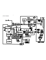
Страница 18: ...4 1 SET BLOCK DIAGRAM 4 1 ...
Страница 19: ...5 1 SET BLOCK DIAGRAM 5 1 ...
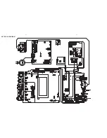
Страница 21: ...6 2 6 2 LAYOUT DIAGRAM DISPLAY BOARD TOP VIEW ...
Страница 22: ...LAYOUT DIAGRAM DISPLAY BOARD BOTTOM VIEW 6 3 6 3 ...
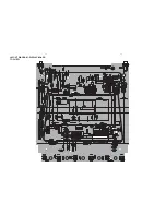
Страница 27: ...8 2 8 2 LAYOUT DIAGRAM POWER BOARD ...
Страница 30: ...9 2 9 2 LAYOUT DIAGRAM WOOFER OUTPUT BOARD ...

