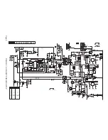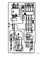
Auxiliary Power Supply (Figure 2)
IC 7510 is the heart of the Auxiliary Power supply. In the Standby mode, VIA the current
sensing and Control circuits, a low power condition is detected by the IC. The IC then goes
into a Burst Mode operation to reduce the power used by the circuit. In the Burst Mode, the
supply will operate at approximately 25 kHz. In full power operation the frequency will be
approximately 66 kHz.
When power is first applied to the set, Start up is supplied to the IC by the internal Start-Up
current through Pin 14. Startup voltage is also applied to the IC to Pin 2 by the AC_IN line
which is tied to the neutral side of the AC line. During normal operation, power is supplied to
the IC by the HOT windings, Pins 1 and 2, of transformer 5504. Output drive from Pin 11 is
applied to the Gate of Transistor 7525. Voltage developed across the current sensing resis-
tors in the Source of 7525 provides current sense information to the IC. When 7525 is
switched Off, the voltage on Pin 1 of 5504 goes High. This winding supplies the operating
voltage the power supply circuit. It also turns Transistor 7567 On causing the Gate of 7525 to
stay Low as long as Pin 1 of 5504 is High. This prevents 7525 from turning On until the field
of 5504 has collapsed.
Regulation is accomplished by monitoring the +3 volt supply. This voltage is fed to Shunt
regulator 7542 which controls the current through opto-isolator 7516. Shunt Regulator 7542
begins conducting when Pin 3 of the IC reaches 2.5 volts. At this point current flows through
the opto-isolator, 7516. The transistor inside 7516 turns On applying a control voltage to Pin
6 of 7510. If a problem should develop in the feedback circuit causing an excessive voltage
on Pin 6, Transistor 7549-2 will turn On, switching Transistor 7532 On. This will a voltage to
the Demag circuit on Pin 7 causing the IC to latch Off. The IC will stay latched until power is
removed and reapplied to the set.
In the Standby mode, the "B" control line from the Hercules Processor is Low. Only the +3,
+3V3, and +6 volt supplies are present. When the set is turned On, the "B" line will go High,
turning Transistors 7509, 7545, and 7535 On. This will switch On the +8VA, +12VA, +8V,
+3V3A, +6VA, and +5V supplies.
In normal operation, voltage from Pin 12 of 5504 is rectified by 6540 to produce a negative
voltage which prevents Transistor 7561 from turning On. If AC is removed from the set, this
negative voltage will disappear. The voltage across the filter capacitors on the +3V line will
turn 7561 On. The Power Down line will then go Low signaling the processor to shut the set
down.
Page 5
Содержание L05HD
Страница 13: ...FIGURE 5 TV SIGNAL PROCESSOR Page 11 ...
Страница 16: ...FIGURE 7 CONTROL Page 14 ...
Страница 19: ...FIGURE 9 DETAILED VIDEO SIGNAL FLOW BLOCK Page 17 ...
Страница 24: ...FIGURE 13 AUDIO OUTPUT Page 22 ...
Страница 27: ...FIGURE 16 WIRING INTERCONNECT Page 25 ...
Страница 28: ...Page 26 SERVICE POSITION ...
Страница 32: ......


