background image

0V5

1R8

TO

7V8

B

8K2

47V3

C

7V5

*

*

*

96V

E

7V5

2V3

B

E

2SC3421

C

E

C

B

1V7

7V2

0V

TO

*

97V3

ROTATION COIL

* *

E

B

E

*

B

C

E

3V8

6V7

8V2

10V8

6V8

12V8

SCAVEM  COIL

7V2

47V2

B1

22n

*

2SA1358

*

3367

I365

9361

3373

16V

10u

2390

2391

100n

400V

2364

4n7

3389

33R

F382

3382

6K8

4n7

UDZS-6V8

2365

6381

I363

7362 BC857B

BC847B

7376

F381

I367

I364

2385

2389

2368

1u0

5331

10R

3362

150K

3390

150K

3391

680K

3393

22K

3392

F362

3387

2362

1n0

10n

2387

BC847B

7361

F363

I348

8K2

3372

I380

I361

3365

10R

I366

3368

820R

330R

3376

5361

F361

+12V_LOT

4

MODE

2

OUT+

7

OUT-

SVR

6

1

VCC

7364

TDA8941P

8

GND

3

IN+

5

IN-

1381

1

2

3

7331

1K8

3375

I344

I345

I342

I343

I341

2383

100n

33R

3388

3363

820R

3369

10R

2367

10u

100V

220R

3377

2361

47n

250V

3371

470R

I371

22u

2363

3366

68K

F360

100V

2376

100n

I347

3361

680R

1R8

3364

1361

1

2

3

I362

I346

4331

2381

100n

68K

1N4148

6361

3370

I372

2384

100n

2382

7363

6K8

3381

I360

3394

6K8

+12V_LOT

I369

I381

I368

Vbatt

+12V_LOT

SVM_ROT

REGION

SET

NAFTA

27VRF-HD

4331

5331

5361

9361

---

1U0 PM10

100MHZ 50R

---

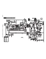
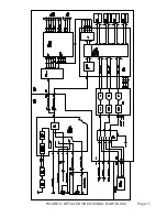
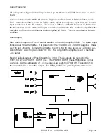
FIGURE 11 - SVM AND ROTATION

Page 20

Содержание L05HD

Страница 1: ...PHILIPS TECHNICAL TRAINING L05HD TRAINING MANUAL PHILIPS CONSUMER ELECTRONICS 64 PERIMETER CENTER EAST PO BOX 467300 ATLANTA GA 31146 7300 MM032205 ...

Страница 2: ...TION 1 POWER SUPPLY 4 AUXILIARY POWER SUPPLY 5 MAIN POWER SUPPLY 7 DEFLECTION SYNC 9 TV SIGNAL PROCESSOR 10 DEFLECTION 10 CONTROL 13 VIDEO SIGNAL FLOW 15 CRT DRIVE 18 AUDIO 21 SIDE JACK PANEL 23 TROUBLESHOOTING TO PANEL LEVEL 23 ...

Страница 3: ... of the pro cessing is performed by the Trident chip IC 7201 The L05HD chassis has two signal processing sections one for the 1fH NTSC and one for 2fH HD processing Whatever signal is applied to the set it is displayed on the CRT in a 1080i format The NTSC tuning system features 181 channels with on screen display The main tuning system uses a tuner a microcomputer and a memory IC mounted on the m...

Страница 4: ...Press the Menu button on the remote and press the Cursor up down button to obtain the following screens Page 2 ...

Страница 5: ... AutoLock Active Control Digi Pic Demo Features T imer Rotation AutoLock Active Control Digi Pic Demo Features Timer Rotation AutoLock Active Control Digi Pic Demo 2 4 Setting up the access code 1 Press the Menu button on the remote to display the on screen menu 2 Press the Cursor up or down buttons until the word features are highlighted 3 Press the Cursor right button to display the features men...

Страница 6: ... the Hercules The 6 volt supply provides power to the IR receiver The Main supply is switched Off via the Standby line When the set is turned On the B line from the Hercules processor goes High switching 7547 which turns 7535 7509 and 7545 On The 3V3A 6VA 12VA and 8VA supplies are then switched On The load placed on the Aux Power supply will cause it to switch to the full power mode At the same ti...

Страница 7: ...ents 7525 from turning On until the field of 5504 has collapsed Regulation is accomplished by monitoring the 3 volt supply This voltage is fed to Shunt regulator 7542 which controls the current through opto isolator 7516 Shunt Regulator 7542 begins conducting when Pin 3 of the IC reaches 2 5 volts At this point current flows through the opto isolator 7516 The transistor inside 7516 turns On applyi...

Страница 8: ...BC857B 7532 I533 I545 RGP10D 6533 33K Vaux_GND 5521 3592 IMX1 1 2 MainSupplyGndA Vaux_GND 7549 2 7 8 9 HEATSINK 0088 1 10 11 12 2 3 4 5 6 1 2 1533 BAS316 6534 3587 2K2 2580 10n I509 3532 I588 3529 1K2 3560 33R BC847BW 7577 BAV21WS 6538 3538 Vaux_GND 2523 1n0 I589 6546 STPS10L60D 100n 2543 HEATSINK 0083 1 2 BAS316 6543 5523 4551 I538 I599 I563 I592 3528 4M7 I534 3585 68K 3535 7545 3 1 2 4R7 SI2305D...

Страница 9: ...igh Transistor 7514 is switched On turning 7512 Off This is to prevent 5512 from becoming saturated When the set is turned On the STBY_Con line goes Low switching 7573 Off The VBAT supply is the reference voltage for regulation Since this voltage is missing during startup the Shunt Regulator 7571 is turned Off The voltage on Pin 6 of 7511 goes Low which turns the drive from the IC On When the set ...

Страница 10: ... 5564 1 4 2 3 4 5 8 1 DMF2405H60 I501 5502 I513 9506 I561 3500 3M3 3516 2505 5 8 9 13 14 15 16 17 18 2 3 4 5512 10 11 12 1M5 3504 2503 2n2 I502 F573 1K0 3515 F503 I527 Audio_Gnd 2502 PFC5000 1501 1 2 3M3 1505 F506 3501 22u 5563 AUDIO_GND2 1510 2574 1n0 1500 9513 9512 3509 2R0 2n2 2504 I522 9511 TCET1103 G 7513 1 4 3 2 3508 220R 7512 22u 2511 2562 50V F563 470p 2565 F541 I562 3520 I582 I521 I581 I5...

Страница 11: ...2V5 T1 T5 0V 0V 0V 0V 3V T5 2V5 T3 2V5 2V5 2V5 1V9 2V5 2V5 0V 2V5 3V3 2V5 2V5 2V5 2V5 2V5 2V2 6V 220R F208 3203 26 37 35 176 28 36 34 180 31 6 27 177 5 179 178 171 170 169 168 167 166 165 4 175 29 6930 DPTVSVP DDP DAC CPU 7201 2 172 560R 3221 AGND5 F287 2225 100n 7203 BC847B BC847B 7204 2217 100n 100n 2220 V 4203 2224 100n F207 3229 180R 3228 220R 3223 100R 220R 3207 4202 2239 100n 2219 100n 2222 ...

Страница 12: ...ed by the Hercules Processor on the Family Board via the I2C buss on Pins 10 and 11 Transistors 7226 and 7227 levels shifts the I2C buss level between 5 and 3 3 volts Geometry and Drive settings are stored in the Memory IC located on the Family Board Deflection Figure 6 Horizontal drive from 7221 is fed to Transistor 7404 located on the Family board This drive circuit has two power sources During ...

Страница 13: ...FIGURE 5 TV SIGNAL PROCESSOR Page 11 ...

Страница 14: ...D GND_HOR 9490 3478 10R 3472 2494 470p 3453 56K 100K F453 3408 I455 F483 2u2 2466 100R 3489 470u 2449 CRT_GND 12V_LOT 6453 5458 I466 RGP10G CRT_GND F457 3414 4R7 GND LINEDRIVE 12V_LOT CRT_GND 470u CRT_GND VT_Supply GND_EW 2460 5459 560n 150R 3413 3480 Vbatt F452 GND_EW 3459 680K 3441 100R I473 2412 2488 100n I423 2464 2426 470p 10K 3497 6464 BZX384 C27 CRT_GND GND_DEF I465 10K 3438 I436 2448 470p ...

Страница 15: ...te sensor are powered by the 3 3 volt supply The customer communicates with the Hercules via the Remote sensor and Power switch located on the Front Control panel The power supplies are switched On via the STBY CONT and B lines The TV Controller is reset by the C control line The I2C bus communicates with the EEPROM 7601 Tuner 1000 TV Controller 7206 Trident 7201 A D 7210 TV Display Processor 7221...

Страница 16: ...FIGURE 7 CONTROL Page 14 ...

Страница 17: ...panel which detects Closed Caption text or teletext This IC also generates the OSD On Screen Display If the signal applied to the set is a 2fH signal or better it is applied to either the YpbPr Component input or the HDMI input These signals are fed to a selector switch located on the HD panel IC 7205 The selected component or RGB signal if fed to the A D converter IC 7210 This signal is fed to th...

Страница 18: ...IC 7201 rescales the picture to 1080i Component video is inserted into the YPbPr input located on the Family board The HDMI panel converts the HDMI signal into an analog YPbPr format Both of these signals are fed to the Switch 7205 which selects between the two The selected signal is fed to IC 7210 which performs an A D conversion This 24 bit signal is fed to 7201 The Scaler Trident IC con verts t...

Страница 19: ...FIGURE 9 DETAILED VIDEO SIGNAL FLOW BLOCK Page 17 ...

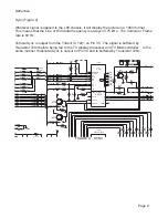
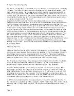
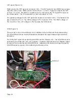
Страница 20: ...e 200VA voltage on Pin 5 powers 7330 The VBAT voltage on Pin 3 and the 12V_LOT voltage on Pin 6 powers the SVM circuit SVM Figure 11 There are two coils on the deflection coil in addition to the Vertical and Horizontal winding The SCAVEM coil Scan Velocity Modulation sharpens the edges between light and dark transitions The SVM_ROT signal drives both the SCAVEM and the Rotation coil The SCAVEM cir...

Страница 21: ...3334 1K0 F339 4334 2334 I339 F334 I332 3n3 2353 4330 680p 2352 3329 100R 4329 F340 I333 I335 I331 1K0 3332 100R 3328 F354 F338 I334 I336 6331 BAV21 100R 3335 3333 100R 1332 I330 I351 2350 2333 1n0 9360 F335 HEATSINK 0330 2331 10n F332 4328 1K0 3336 3337 F353 F352 3330 100R 2351 10u 3354 1K5 2332 F341 100R 3360 1352 BAV21 6333 I340 F333 I338 9337 I353 7 100R 3331 1 2 3 4 5 6 1351 8 9 I352 F331 1 10...

Страница 22: ...n 2387 BC847B 7361 F363 I348 8K2 3372 I380 I361 3365 10R I366 3368 820R 330R 3376 5361 F361 12V_LOT 4 MODE 2 OUT 7 OUT SVR 6 1 VCC 7364 TDA8941P 8 GND 3 IN 5 IN 1381 1 2 3 7331 1K8 3375 I344 I345 I342 I343 I341 2383 100n 33R 3388 3363 820R 3369 10R 2367 10u 100V 220R 3377 2361 47n 250V 3371 470R I371 22u 2363 3366 68K F360 100V 2376 100n I347 3361 680R 1R8 3364 1361 1 2 3 I362 I346 4331 2381 100n ...

Страница 23: ...nel 20 watt amplifier Audio output Main audio is output on Pins 68 and 69 and fed to the audio amplifier 7990 The audio ampli fier is a dual 10 watt amplifier It is powered by the VAUDIO and VAUDIO supplies These are 16 and 16 volts To mute the amplifier the VOL_MUTE line goes Low switching tran sistor 7992 Off switching transistor 7991 On The output of the amplifier is fed to the Side Jack panel ...

Страница 24: ...FIGURE 13 AUDIO OUTPUT Page 22 ...

Страница 25: ...nserted Finding the defective panel Figures 15 and 16 When troubleshooting the set the defective panel requiring replacement or additional repair must be located The Power supplies Deflection 1fH inputs and Audio outputs are located on the Family board The 2fH CRT drive and Deflection drive circuits are located on the Trident board If the set turns On without a picture or sound first check the pow...

Страница 26: ... INTERFACE J MAINS CORD MAINS SWITCH 2P 7P Warning Some models have tact switch 5P 5P 7P 1693 7P 1207 1005 7P 1252 2P 1451 3P 1682 2P 1401 5P 1254 3P 1280 4P 1278 1280 5P 1351 3P 1361 3P 1381 1504 LOT TUNER 1223 HDMI PANEL M 4P 1352 1335 CRT SOCKET 3P COMPAIR CONNECTOR TRIDENT PANEL T 1223 4P 1250 12P 1251 10P 1202 5P 1250 12P 1251 10P 5P 1340 1206 4P 1533 12P 1221 6P 1220 7P 1228 6P 1222 6P 1222 ...

Страница 27: ...FIGURE 16 WIRING INTERCONNECT Page 25 ...

Страница 28: ...Page 26 SERVICE POSITION ...

Страница 29: ...er SAM press 0 6 2 5 9 6 Info on the remote control Use the cursor up and cursor down buttons to highlight a selec tion Press the cursor right cursor left buttons or enter a value to make changes Refer to the Service manual for additional information on the SAM FIGURE 17 SERVICE ALIGNMENT MODE Page 27 ...

Страница 30: ... INT CVBS signal from Tuner CVBS MON CVBS monitor signal CVBS TER OUT CVBS terrestrial out DAC Digital to Analogue Converter DFU Directions For Use owner s manual DNR Dynamic Noise Reduction DRAM Dynamic RAM DSP Digital Signal Processing DTS Digital Theatre Sound DVD Digital Video Disc EEPROM Electrically Erasable and Programmable Read Only Memory EPLD Electronic Programmable Device EXT EXTernal s...

Страница 31: ... data for example options OSD On Screen Display Progressive Scan Scan mode where all scan lines are displayed in one frame at the same time creating a double vertical resolution RAM Random Access Memory RC Remote Control transmitter RC5 Remote Control system 5 the signal from the remote control receiver RGB Red Green and Blue The primary colour signals for TV By mixing levels of R G and B all colo...

Страница 32: ......
Отзывы: